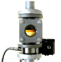
Vision Systems for Real Time Water System Analysis and Treatment

canty particulate analysis
Image courtesy of JM Canty
Effective monitoring of intake and effluent flows presents a difficult challenge to the water treatment industry in many ways. Real time knowledge of water condition can inform downstream or upstream processes how to change treatment regimes to affect a consistent, positive outcome in relation to standards. FOG’s are a constant headache in wastewater treatment. Particulate can build in pipelines causing significant flow reductions and overflows.

Water drawn from rivers, lakes and shed areas for human and industrial uses can become laden with particulate due to weather or other natural events which can overload filtering capacities intended to purify the water prior to use. Invasive species such as the zebra mussel can collect at intake and outlet pipes and reduce volume flows. Vision technology can provide real time monitoring solutions and, in addition to providing a visual verification of process conditions, has resolved the longstanding fouling issues instruments have generally had in extreme processes. 

Analysis of particulate based on size, shape and percent solids can indicate varying conditions of feed water to operators who can then optimize treatment or close intakes while the upset conditions prevail, thereby preserving water quality. This technology also provides the user with visual verification of process conditions and together with Ethernet transmission protocol, view and analysis can be provided at any point throughout local or wide area networks.

Read, or download, the full research paper (courtesy of Canty Process Technology) below:

Industrial Temperature Sensors: Basics of Thermocouples

industrial thermocouples
Industrial thermocouples
(courtesy of Applied Sensor Technology)
Thermocouples are the most widely used industrial temperature sensor found in industrial processes today. They are rugged, relatively inexpensive to manufacture, and provide fairly good accuracy.

Thermocouples operate on the "Seebeck Effect", which is the phenomena whereby two dissimilar metal conductors (wires), joined at two points, with one point kept at a known constant temperature, produce a measurable voltage difference between the two conductors.

Thermocouple types - such a type J, type K, type R, and type S - refer to the alloy combinations used for the conductors and are based on standardized color designations. 

Thermocouples are used widely in industrial processes in industries such as power generation, primary metals, pulp and paper, petro-chemical, and OEM equipment. They can be fabricated in protective wells, and can be housed in general purpose, water-tight, or explosion-proof housings.

The following video provides a basic visual understanding of thermocouple wire, how a T/C junction is determined, and also discusses thermocouple connectors, polarity and some aspects of construction (such as grounded vs. ungrounded vs. open tip).

Pressure and Temperature Transmitters/Switches - Safety Right Out of the Box

safety transmitter
UEC Safety Transmitter
Many process safety experts are looking for sustainable ways to help their personnel improve their safety critical loops, do it in the most cost-effective way possible, and with a minimum of complexity. The problem is the traditional approaches to deploying a full blown safety system are expensive and very complex, and still may not deliver the needed risk reduction for some safety critical systems and loops.

In the sensor subsystem for example, United Electric’s certified safety transmitter for pressure or temperature has opened up a new, less costly, less complex path for designers, I&C engineers, and maintenance personnel. It has something very unique. In addition to a 4-20 mA output, is has an embedded programmable high-capacity relay which exida has certified as a safety variable output. Now you have a device that provides designers the option of a hard wired trip in less than 100 milliseconds, with a tenth of a percent repeatability, while still providing the monitoring functions of a traditional continuous analog output.

For equipment under control, like pumps and compressors that require protection, or processes where rapid excursions can initiate dangerous events, this unique pressure and temperature transmitter, (certified for use in SIL2 safety instrumented functions, with SIL3 capability)  is addressing process safety time constraints, coupling issues with PLC and DCS’s, and adding diversity to the safety instrumented function.

The safety transmitter has a safe area fraction of 98.6% with breakthrough, automatic, self diagnostics and is one-third the cost of typical certified process transmitters.


An Introduction to Industrial Pressure, Differential Pressure, and Temperature Switches

pressure switch
Pressure switch with large diaphragm
Most industrial applications require the monitoring of pressure and temperature of a process. Pressure and temperature measurement can be accomplished either by transmitters, gauges or by switches.
This post will provide a quick introduction of industrial electromechanical pressure switches and temperature switches.

An industrial pressure and temperature switch is made up of the three main components: 1) the sensor, 2) the housing and 3) the switching element.

The correct combination of each component assures proper application of the device for its intended use.

Sensor

The sensor is located above the pressure port and process connection. For pressure and differential pressure switches, there are several varieties of pressure sensors to choose.  The most common types of pressure sensors are:

Metal Bellows - an accordion-like device that provides linear expansion and contraction based upon the application of pressure or vacuum. Bellows are excellent sensors because they provide good overall pressure range and are fairly sensitive to small changes in pressure.

Piston - A rod and o-ring combination that moves linearly in direct response to applied pressure. Piston sensors are normally only applied to only very high pressure ranges. They have very small surface areas and wide deadbands (the change in pressure required to change the position of the switch output).

pressure switch
Pressure switch with piston sensor
Diaphragm - A thin, elastomer or metallic membrane, often with a rolled lip that allows for greater movement. The diaphragm has a large surface area and provides the most sensitivity to pressure change, making it ideal for low to mid-range pressure sensing.

Housing

Housings are classified and selected based on the atmosphere in which they’ll be used. Housing ratings are classified by several national and international agencies such as NEMA and CENELEC. Very generally put, housings can be rated as general purpose, dust & water resistant, water tight, corrosion resistant and hazardous (explosive) environments. Proper selection of the housing is important to the operation and life expectancy of the device. In hazardous environments, proper selection is absolutely critical. If unsure about the housing classification, consultation with an applications expert is required.

Switching Element

The switching element refers to the signaling device inside the enclosure that responds to the movement of the sensor. It can be either electrical or pneumatic, and provides an on-off signal (as opposed to an analog, or proportional signal produced by transmitters).

differential pressure switch
Differential pressure switch
The switching element is most times a “micro” type single pole, double throw (SPDT) electrical switch. These microswitches come in many configurations and electrical ratings, such as double pole, double throw (DPDT), 120/240 VAC, 12VDC, 24VDC, and hermetically sealed.

For the switching element and the sensor, it is very important to know the cycling rate (number of on vs. off times over a period of time) the instrument will see. Since both of these elements are mechanical, they will eventually wear out and need to be replaced. Switches are an economical and strong performing choice for low to medium cycle rates. For extremely high cycle rates, the use of solid state transmitters are a better choice.

temperature switch
Temperature switch
Temperature Switches

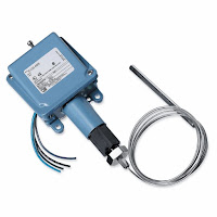
An electromechanical temperature switch (sometimes called a thermostat) is, for the most part, a piston type pressure switch connected to an oil filled capillary and bulb sensing element. The thermal expansion of the oil inside the bulb and capillary creates the pressure and linear movement upon the piston sensor of the switch. The bulb and capillary elements can be supplied in copper or stainless steel, and at various lengths.

There are many more details to selecting and applying electromechanical pressure and temperature switches. This post is only intended to provide a very general introduction. It is always suggested to discuss your application with a qualified applications engineer so that you are assured to get the longest lasting, most economical and safest instrument possible.


Basics of Differential Flow Devices

Orifice plate flow meter
(courtesy of Siemens)
The differential flow meter is the most common device for measuring fluid flow through pipes. Flow rates and pressure differential of fluids, such as gases vapors and liquids, are explored using the orifice plate flow meter in the video below.

The differential flow meter, whether Venturi tube, flow nozzle, or orifice plate style, is an in line instrument that is installed between two pipe flanges.

The orifice plate flow meter is comprised the circular metal disc with a specific hole diameter that reduces the fluid flow in the pipe. Pressure taps are added on each side at the orifice plate to measure the pressure differential.

According to the Laws of Conservation of Energy, the fluid entering the pipe must equal the mass leaving the pipe during the same period of time. The velocity of the fluid leaving the orifice is greater than the velocity of the fluid entering the orifice. Applying Bernoulli's principle, the increased fluid velocity results in a decrease in pressure.

As the fluid flow rate increases through the pipe, back pressure on the incoming side increases due to the restriction of flow created by the orifice plate.

The pressure of the fluid at the downstream side at the orifice plate is less than the incoming side due to the accelerated flow.

With a known differential pressure and velocity of the fluid, the volume metric flow rate can be determined. The flow rate “Q”, of a fluid through an orifice plate increases in proportion to the square root the pressure difference on each side multiplied by the K factor. For example if the differential pressure increases by 14 PSI with the K factor of one, the flow rate is increased by 3.74.


A Clean in Place (CIP) Mag Flow Meter with Pasteurized Milk Ordinance (PMO) Approvals

magmeter with PMO approval
Magmeter with PMO approval
(courtesy of SIEMENS)
Dairies have been hampered by a limited selection of flowmeters to process raw ingredients and maximize productivity. Faced with limited choices for instrumentation, the Food and Beverage Industry is always interested in new products and certification. In this case, the product is a "Clean in Place" (CIP) electromagnetic flow meter (Magmeter) with Pasteurized Milk Ordinance (PMO) approvals.

Clean-in-place (CIP) is a method of cleaning the interior surfaces of process equipmentpipes, vessels, and fittings, without disassembly. This is an invaluable technology in the dairy, brewery, beverage, processed foods, cosmetics, and pharmaceutical industries by providing a cleaning process which is faster, far less labor-intensive, more consistent, and with less chemical exposure to workers.

The Pasteurized Milk Ordinance, is published by the Food and Drug Administration further defines minimum standards and requirements for Grade A milk production and processing.

A Magmeter is an excellent flowmeter choice for dairy use because it is unaffected by suspended solids, viscosity, and temperature challenges typically found in food and beverage applications. Additionally, magnetic flowmeters provide:
  • Ease of installation with Tri-clamp fittings.
  • Stainless steel, obstruction less flow performance meets all sanitary requirements and is 3A certified.
  • Suitable for CIP and SIP cleaning.
  • IP67 I NEMA 4X rating that is upgradeable to IP68 /NEMA 6P.
Carrying a PMO approval provides the dairy with confidence and assurance that the magnetic flowmeters have been tested and approved precisely for use in their plant.

For more information, see the document below:

Remote Sensing of Gases Directly in the Process

Electric power plant
Electric Power Plant
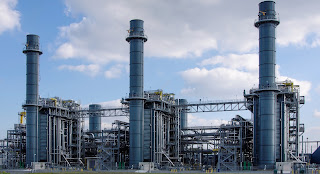
Industrial operations, whether for direct process control or emissions compliance monitoring, have a need for accurate, reliable measurement of specific gas concentrations within a flowing medium. Tunable diode laser spectroscopy, packaged for industrial use, provides a number of substantially positive attributes.

  • Rapid measurement.
  • Can be focused on a specific component of interest.
  • Multi-channel operation provides analysis of several components.
  • In situ installation can provide direct measurements within a stack, pipe, or duct without sample handling or conditioning.
  • Can measure NH3, HF, HCl, H2O, CO, CO2.
  • Internal reference cell provides long term stability.
  • Some models have continuous automatic calibration.
Siemens manufactures a line of tunable diode laser gas analyzers for industrial applications. In the company's own words, here is a basic description of how it works.

As a tunable diode laser-based technology this in-situ device enables high-performance measurements. The sensors (transmitter and receiver) are meant to be mounted directly on the process with no need of sampling systems. Laser light is sent from the transmitter, passing through the process gas, arriving at the detector on the receiver side. The measurements are carried out on-line with a very short response time permitting fast and effective cost-savings in process control. The laser characteristics allow single-line spectroscopy free of interferences. Since the band width of the laser light is extremely narrow, only the gas component of interest will interact with it. Other process influences, such as dust and temperature, are easily eliminated due to the excellent inherent compensation capabilities of this technique.


There is application assistance and more detailed information available from knowledgeable sales engineers in all localities. Combine your process mastery with their product application resources to meet the challenges posed by modern industrial process operation.


Basic Programming for the SITRANS F M Electromagnetic Flowmeter

The video below explains the basics of programming the SITRANS F M electromagnetic flowmeter.

The SITRANS F M MAG 5000 & 6000 are microprocessor-based transmitters engineered for high performance, easy installation, commissioning and maintenance. These transmitters are truly robust, cost-effective and suitable for all-round applications. The MAG 5000 has a measuring accuracy of ± 0.4% of the flow rate (incl. sensor), while the MAG 6000 has a measuring accuracy of ± 0.2% of the flow rate and can be fitted with optional plug-in communication modules.


Other Members of the SITRANS F M MAG Family:

SITRANS F M MAG 1100 is a wafer design sensor in stainless steel with highly resistant liners and electrodes and is designed for the general industry environment. The flangeless wafer design meets all flange standards. The SITRANS F M MAG 1100 is used in all industries where the corrosion-resistant stainless steel housing and the highly resistant liner and electrodes fit even the most extreme process media.

The SITRANS F M MAG 1100 F sensor is especially designed for the food & beverage and pharmaceutical industries and is available with hygienic and flexible process connections. It meets all sanitary requirements and is 3A certified and EHEDG approved.

The SITRANS F M  MAG 5100 W  with its patented liners of hard rubber NBR or ebonite and EPDM is a sensor for all water applications such as ground water, drinking water, cooling water, waste water, sewage or sludge applications.

SITRANS F M MAG 3100 is an electromagnetic flow sensor with a large variety of liners, electrode material and with grounding electrodes as standard, all this ensures a perfect fit for almost every flow application.
Also, measuring electrodes which are capable of withstanding the most extreme processes and various liners are available.

The SITRANS F M  MAG 3100 P sensor  is designed to meet the most common specifications within the chemical and process industries. It has PTFE or PFA liners and Hastelloy electrodes being the ideal combination. The fully welded construction provides a ruggedness that fits almost every flow application.

The SITRANS F M MAG 6000 I and the SITRANS F M MAG 6000 I Ex de transmitters have an measuring accuracy of + 0.2% of the flow rate and are designed to meet the demands of the process industry. Both versions are based on a microprocessor with a built-in alphanumeric display.

High Performance, Low Cost, Industrial Safety Device

Series One Safety Transmitter
Safety Transmitter
Sadly, There are too many recent examples of catastrophic industrial accidents. New safety technologies exist today that can prevent or mitigate future disasters. The philosophy of safety is changing - the focus on plant safety has changed from reactive to a proactive approach. End users have a new sense of urgency toward safety processes.

The United Electric Controls (UE) Series One is a SIL-certified (SIL stands for safety integrity level) transmitter designed solely for safety, alarm, and shutdown applications, with reliability, speed, and fewer nuisance trips. It is also designed for both greenfield and brownfield installations, and is cyber secure.

A typical safety loop consists of sensors (such as a pressure transmitter), controllers, and final control elements. Most SIL-rated pressure transmitters require 300ms to communicate with the controller and up to 500ms for the controller to send a signal to the final control element (such as a valve). This may not be fast enough for critical applications. By connecting the One Series Safety Transmitter directly connected to the final control element, the signal speed is reduced to 100ms - a huge time savings when you're in the midst of a disaster. When used with blowers, pumps and compressors, the One Series makes up a complete safety system with a self-contained sensor, controller, and final control element (the switch) capable of SIL2 without additional safety instrumented function (SIF) components.

The below document provides detailed information about the Series One.


For more information, contact:

Ives Equipment
877-768-1600
www.IvesEquipment.com


Township Water Authority Uses Ultrasonic Clamp-On Flowmeters to Avoid Surcharges for Exceeding Peak Limits

Ultrasonic Clamp-On Flowmeter
(courtesy of Siemens)
Reprinted with permission from Siemens Process Instrumentation

A suburban township buys their drinking water from a major municipal water district. The township’s water distribution system network has four connections to the larger municipality’s water transmission main. The municipality has many customers and has implemented contracts with each of its wholesale customers that limit the peak flows and the time of day in which they may occur. If the wholesale customer exceeds the limit, they are assessed significant surcharges.

Because of the potential surcharges, the wholesale customers can financially justify investing in solutions to better control their water demand, minimize the usage peaks, and control what time of day they occur. These measures include elevated water storage towers, as well as control valves at each of the connections to the municipal provider’s transmission main.

Challenge

The major municipal water district owns and operates “metering pits” with magmeters immediately upstream of the control vaults owned by each customer. However, as a rule, the signals from these meters are not made available to the any wholesale customers on a real time basis. Wholesale water customers are only given datalog summary reports from these meters on a routine schedule for billing purposes.

Without a method of measuring flows or getting flowrate data from the water district in advance, the township customer had no means of knowing, in real-time, the amount of flow they drew from the transmission main. Therefore, they did not know if or when they were exceeding the contractual peak flowrate limits and incurring significant surcharges from the water district until they were billed.

The township customer needs to know the flowrate at each of its four connections to the transmission main so they may control how much is being drawn at each site. They also need the total flow from the municipality’s transmission main, so they do not exceed their contractual peak demand.

The control vaults were initially installed without flowmeters. The intention was to use control valve position and upstream/ downstream (differential) pressure readings to estimate the flow through the control valve using the characteristic curve of the valve. This proved to be too complicated and cumbersome for their SCADA system to effectively implement.

Solution

The local Siemens representative worked with the township and their engineer to find a solution to measure the flow rate and totalize the volume of flow at each of the customer’s control vault sites. The most significant challenge was the piping configuration. All of the vaults were previously constructed without provisions for a flowmeter. The control valve vaults are very tight. The Siemens representative used a Siemens ultrasonic clamp-on flowmeter demo kit to demonstrate the technology to the customer, and prove that it would reliably meet their objectives. The vault with the worst piping configuration was selected for the demonstration. That would demonstrate that if the flowmeter would work in the worst site, it would work at the other three sites as well. However, if the Siemens flowmeter didn’t work in that site, the township would need to look at alternate, more costly, flow measurement technology for a solution. Within minutes of arriving on site, the unit was installed and providing reliable readings. The unit was allowed to log for a period of three days. After that, it was retrieved and compared to the readings from a competitive magmeter in the municipal water provider’s metering pit.

The logger on the Siemens clamp-on flowmeter provides helpful information on the quality of the velocity and flow measurements. This logged information helped establish and solidify the confidence of the owner and the engineer that the Siemens clamp-on meter would work for these applications.

Four key reasons the customer chose Siemens flowmeters:
  • The Siemens clamp-on flowmeter has the capability to make the tough measurements and provide information on the quality of those measurements. 
  • The attentive, professional and knowledgeable service they received from the local Siemens representative was well supported by Siemens personnel. 
  • The local representative provided the field service to install the transducers on the pipe, and commission the transmitters. 
  • The local representative conducted the demonstration and assisted the township engineer with their evaluation of the ultrasonic clamp-on flowmeter vs. magmeters owned by the water district. The major water district supported the Siemens ultrasonic clamp-on technology used by the township customer after they attended a Siemens Level & Flow Seminar held in their district. 
Benefits
  • Cost Savings - If they were not able to use the Siemens ultrasonic clamp-on flowmeters, the customer would have had to excavate and install a below-grade vault to house a magmeter and associated isolation and by-pass valves, along with conduit and wiring, at each of these four sites. This would have required cutting the water pipe and then going through a cumbersome disinfection process, both of which would have required lengthy permitting and costly testing. Further, some of the sites really had little or no room to accommodate such a structure or piping modifications. It is estimated these modifications would have totaled over $250,000. In comparison, the customer ended up spending $25,000 for the meters, and field service to install some conduit from the pipe to an existing above grade SCADA panel. 
  • Time Savings - The customer had already made improvements to the distribution system and installed four new control vaults. Their construction contracts were closing and they could not use their water tower until the new flow controls were added. Time was a critical factor. The customer saved 3-6 months in time by using the Siemens clamp-on flowmeters instead of having to construct new vaults to house magmeters. 
  • Improved Process Reliability - Now that the meters are in place, the customer can control how much water they are taking from the water district at each of these four locations, and ensure they do not exceed their contractual peak. They can now also properly manage the fill and draw of their elevated storage tank to offset peak demands, and fill/store during periods of low demand. 

Step-by-Step Instructions for Installing a Samson 3277 Actuator

The Samson 3277 is a pneumatic linear actuator suitable for attachment to Samson Series 240, 250, 280 and 290 control valves, as well as the type 3510 Micro-flow valves. Designed with a rolling diaphragm and internal springs, the Samson 3277 is popular because of its low overall height, fast response, low friction, and its ease to maintain. Attaching the actuator, or replacing one, can be done in minutes, without the need of special tools.


This video provide step-by-step instruction on how to install the 3277 actuator.


The Coriolis Principle and It's Use in Flow Measurement

Image courtesy of
Wikipedia
The Coriolis effect acts on a medium that is accelerated through a rotating system, like a ball on a rotating disk its movement is straight, however, if the observer turns with the disk the ball is apparently deflected (see image).

The same effect occurs with a water hose that rotates around its own axis, like a skipping rope. As soon as water flows through the host also twists. The twisting is stronger or weaker, depending on the amount of water flowing through the hose.

Coriolis flow meters function according to the same principle (measuring the force resulting from acceleration caused by mass moving toward, or away from, a center of rotation).
Oscillation with flow
(courtesy of Wikipedia)
Oscillation without flow
(courtesy of Wikipedia)
 
The Coriolis effect also appears with an oscillating movement, and in a Coriolis flowmeter, two symmetric metal tubes are set vibrating by an internal driver coil. The tubes oscillate with a resonance frequency similarly to that of a tuning fork.

The oscillation is measured precisely by two pick-ups at the inlet and outlet sections. If liquids or gases flow through the tubes, a phase shift occurs the pickups measure the spatial and temporal displacement (twist). The amount of twist is proportional to the mass flow rate of fluid passing through the tubes. The greater the amount, the stronger the tubes oscillate outwards.

Finally, sensors and transmitters are used to measure the twist and create a linear flow signal as an output for monitoring and control.

This video, although marketing oriented, does a great job illustrating the Coriolis effect and how Coriolis flowmeters measure mass flow (the video references the Siemens SITRANS FC430 as the example).


Ultrasonic Level Measurement


Ultrasonic level instruments measure the distance from the transmitter (located at some high point) to the surface of a process material located farther below using reflected sound waves. The frequency of these waves extend beyond the range of human hearing, which is why they are called ultrasonic. The time-of-flight for a sound pulse indicates this distance, and is interpreted by the transmitter electronics as process level. These transmitters may output a signal corresponding either to the fullness of the vessel (fillage) or the amount of empty space remaining at the top of a vessel (ullage).

Ullage is the “natural” mode of measurement for this sort of level instrument, because the sound wave’s time-of-flight is a direct function of how much empty space exists between the liquid surface and the top of the vessel. Total tank height will always be the sum of fillage and ullage, though. If the ultrasonic level transmitter is programmed with the vessel’s total height, it may calculate fillage via simple subtraction:

Fillage = Total height − Ullage

If a sound wave encounters a sudden change in material density, some of that wave’s energy will be reflected in the form of another wave in the opposite direction. In other words, the sound wave will “echo” when it reaches a discontinuity in density20. This is the basis of all ultrasonic ranging devices. Thus, in order for an ultrasonic level transmitter to function reliably, the difference in densities at the interface between liquid and gas must be large. Distinct interfaces of liquid and gas almost always exhibit huge differences in density, and so are relatively easy to detect using ultrasonic waves. Liquids with a heavy layer of foam floating on top are more difficult, since the foam is less dense than the liquid, but considerably denser than the gas above.

A weak echo will be generated at the interface of foam and gas, and another generated at the interface of liquid and foam, with the foam acting to scatter and dissipate much of the second echo’s energy.

The instrument itself consists of an electronics module containing all the power, computation, and signal processing circuits; plus an ultrasonic transducer to send and receive the sound waves. This transducer is typically piezoelectric in nature, being the equivalent of a very high-frequency audio speaker.

The ISA-standard designations for each component would be “LT” (level transmitter) for the electronics module and “LE” (level element) for the transducer, respectively. Even though we call the device responsible for transmitting and receiving the sound waves a transducer (in the scientific sense of the word), its function as a process instrument is to be the primary sensing element for the level measurement system, and therefore it is more properly designated a “level element” (LE).

This photograph shows a typical installation for an ultrasonic level-sensing element (LE), here sensing the level of wastewater in an open channel:


If the ultrasonic transducer is rugged enough, and the process vessel sufficiently free of sludge and other sound-damping materials accumulating at the vessel bottom, the transducer may be mounted at the bottom of the vessel, bouncing sound waves off the liquid surface through the liquid itself rather than through the vapor space. As stated previously, any significant difference in material densities is sufficient to reflect a sound wave. This being the case, it shouldn’t matter which material the incident sound wave propagates through first:

This arrangement makes fillage the natural measurement, and ullage a derived measurement (calculated by subtraction from total vessel height).

Ullage = Total height − Fillage

As mentioned previously, the calibration of an ultrasonic level transmitter depends on the speed of sound through the medium between the transducer and the interface. For top-mounted transducers, this is the speed of sound through the air (or vapor) over the liquid, since this is the medium through which the incident and reflected wave travel time is measured. For bottom-mounted transducers, this is the speed of sound through the liquid. In either case, to ensure good accuracy, one must make sure the speed of sound through the “timed” travel path remains reasonably constant (or else compensate for changes in the speed of sound through that medium by use of temperature or pressure measurements and a compensating algorithm).

For more information, check out this online document or visit Ives Equipment at www.ivesequipment.com.


(Attribution to Tony R. Kuphaldt under Creative Commons Attribution 3.0 United States License)

Introduction to Electrically Actuated Valves (Motor Operated Valve or MOVs)

electric valve actuators
Electric valve actuators for MOVs
The two most common methods of opening and closing industrial valves are by pneumatic actuators and electric actuators. This video introduces the viewer to electric valve operation.

Commonly known as "motor operated valves", or MOVs, electric operators can be fitted to any quarter-turn valve (90 deg. rotation) (such as a ball, butterfly or plug valve), or linear movement valve (such as a globe or gate valve).

Most often electric actuators are used where electric power is readily available and a pneumatic air systems are not. They are available in a variety of voltages and torque outputs for various size valves. Accessories such as limit switches, positioners, and hazardous area enclosures are available as well.

Simplifying Plant Safety instrumentation

White paper courtesy of United Electric Controls

Safety implementation typically is done by a group that includes plant instrument engineers and technicians, who are charged with finding simple and reliable solutions. Often, these situations involve the question of when to shut a process down. Such decisions frequently hinge on key process variables such as flow, level, temperature and pressure. these must be in a specified range at various locations within chemical and petrochemical plants, refineries and power plants, including everything from critical process vessels to eye wash stations.

For such point safety applications, a properly designed and implemented digital switch with self-diagnostics can be an important part of the answer. As an element of a multiple technology solution, a digital switch-based approach can help eliminate common-mode failures, significantly improve response time, achieve needed safety integrity levels (SILs), and simplify plant safety instrumentation.

To read the entire white paper, see the embedded document below:

Electronically Enhanced Solenoid Valves - Voltage Ranging Valves

Voltage Ranging Valves
Electronically Enhanced
Solenoid Valves
Voltage Ranging Valves
(courtesy of ASCO)
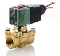
New power management technology is rewriting industry standards for reliability and power consumption of solenoid valve coils. The new technology solenoid valves accepts both AC and DC voltages while improving performance. Available in 2-way, 3-way and 4-way, these solenoid valves are designed to handle most fluid control applications.

The enhanced valves are designed to be drop in replacements for existing valves. There is no change to functional attributes such as flow, pressure, ambient & fluid temperatures or physical attributes such as envelope size and face-to-face dimensions. If you're looking to just switch out a coil,  enhanced coil kits are direct replacements for the old coil kits.

Here are the benefits to end customers:

Lower Power Consumption
  • 1.0 watt (DC version) & 1.5 watts (AC/DC versions)
  • Lowers energy cost up to 80% compared to standard solenoid valves 
RoHS 2 Compliant
  • Satisfies CE Directives 2002/95/EC and 2001/65/EU (RoHS 2) for the restriction of hazardous substances 
Supervisory Current Compatible
  • Suitable for systems employing supervisory currents not exceeding the following drop-out currents:
    • 20mA (12-24V DC), 15mA (24-120V AC/DC) and 7mA (100-240V AC/DC) 
  • Also suitable with devices having leakage currents not exceeding the drop-out currents noted above. 
Broad Voltage Ranges Reduce Inventory
  • Available in 24-120V AC/DC, 100-240V AC/DC & 12-24V DC 
  • Covers hundreds of global voltage requirements
  • Simplifies product selection and reduces complexity
  • Lowers inventory cost by eliminating need to stock both AC & DC products
  • Includes 125VDC battery (AC/DC versions) & 24VDC battery (DC version) 
DC Performance Increased Up to 500% To Match AC Ratings 
  • Transition from AC to DC without sacrificing performance
  • Eliminates the need for separate AC & DC output cards
  • Simplifies control schemes 
Integrated Surge Suppression
  • Prolongs the life of the coil by suppressing external voltage spikes
  • Lowers system cost by eliminating the need for additional surge protection 
Fit For Use In Rugged and Demanding Environments
  • Wide ambient temperature range for hot and cold environments
  • Enclosure Types 1 through 4X for indoor and outdoor applications o Optional Class 1, Division 2 coils available for hazardous locations 
No AC Hum
  • Ideal for applications requiring quiet operation

High-Temperature Capable Flammability Analyzer Increases Profit at Plastics Product Manufacturer

flammability analyzer
Flammability analyzer designed for
tough industrial applications
(courtesy of Control Instruments Corporation)
The customer is global supplier of vibration damping and sealing products for the automotive, consumer electronic and industrial markets that sells elastomer-coated metals, gaskets, brake shims and automotive and brake noise insulators. They also manufacture a variety of sealing materials, such as deck plates, oil filter adaptors, water outlets, pumps, relief valves, and rear cam and surge tank covers.

In their process solvents are applied to a web material. The web material contains PTFE and/ or rubber based adhesives and at times silicone. The main solvent component used is MEK which is not a high flash point solvent. Flammability analyzers were being used to monitor the flammability levels of the varying solvent levels in the zone’s atmosphere.

The flammability analyzers were mounted fairly far from the oven because of operating temperatures, and subsequently had long sampling lines. The last three zones were very challenging due to the distance and the use PTFE, silicones and other resins. Because the lines were so long, they were clogging from VOCs and vaporized web material and required the line to be shut down and cleaned. The downtime meant loss of production and loss of profits. The customer tried adding end-of-line filters on all sample tubing, which helped, but didn't solve the problem.

To solve the problem, the customer upgraded to a new flammability analyzer (a CIC model SNR674) rated for operating temperatures high enough (392 F) to keep all the elements in a vapor state and designed for use in a dirty environment. Theses new flammability analyzers are mounted directly on the oven wall eliminating the long sample lines. By keeping the sample lines as short as possible they were able to minimize the VOC condensation and eliminate the clogging.

For more information, contact:

Ives Equipment
(877) 768-1600
www.ivesequipment.com

Selecting Valves Used in Wine Production and Craft Brewing

wine and brewing process
Valves and Sensors
used in wine and
beer making.
Small wineries and craft breweries are appearing all over the Mid-Atlantic region. While mostly small in scale, these producers all have to refine their fermentation, filtering, and bottling processes using valves and process sensors. Controlling temperature, pressure, and flow is critical to any winery or brewery for product consistency and quality. 

Here is an excellent white paper by Scott Cameron of ASCO Valve describing the types of valves used and how they're used.


Level Phase Split Detection and Measurement

Phase Level Detection
Phase level detection.
Need a system for continuous interface measurement? This system will monitor the emission phase and detect when phase A/B occurs, avoiding any flow of the emulsion into the incorrect area. When phases are separated, the system allows for tight control, which increases efficiency of separation of liquids A&B.

This system provides the ability to remotely view a process that may not normally be watched. Multiple viewing stations may be linked to the system output so various departments may monitor a process. Customers may purchase video monitors, amplifiers or screen splitters to enhance the system.

 
  • Ethernet systems allow the additional functionality of being able to remotely view through a Gigabit network system. Users can have access to live system images from their office networked computer. 
  • Software is available for customers that require additional functionality over simple viewing of a live image. Liquid level, color of different phases, and visual verification. 
System verifies the color of fluid in phase split and sends an output signal locating specific points of the interface. All measurements can be recorded and archived for a historical record. 


Monitor phase split in batch mode on organic droplets for increased product recovery. As the droplets appear the system warns of organic phase and the upcoming emulsion. The amount of early droplets and their retraction time will indicate the completeness of the separation. Once the split is identified and stopped, the operator has a visual verification from the video monitor. The color can then be analyzed to ensure there is no inversion.

For more information, contact:

Ives Equipment
601 Croton Road
King of Prussia, PA 19406
(877) 768-1600
www.ivesequipment.com

Basics of Self-Regulating Heat Trace Cable

Heat Tracing Layout
Self-regulating Heat Tracing Layout
Self-regulating heater cable is a parallel circuit electric heater strip. An irradiation cross- linked conductive polymer core material is extruded over the multi-stranded, tin-plated, 18-gauge copper bus wires. The conductive core material increases or decreases its heat output in response to temperature changes. A thermoplastic elastomer dielectric jacket is then extruded over the conductive core. A copper braid is installed over this jacket providing a continuous ground path. A UV stabilized thermoplastic elastomer overjacket is provided to cover the braid for wet applications and exposure to the sun.

Principle of Operation:

The parallel bus wires apply voltage along the entire length of the heater cable. The conductive core provides an infinite number of parallel conductive paths permitting the cable to be cut to any length in the field with no dead or cold zones developing. The heater cable derives its self- regulating characteristic from the inherent properties of the conductive core material. As the core material temperature increases, the number of conductive paths in the core material decreases, automatically decreasing the heat output. As the temperature decreases, the number of conductive paths increases, causing the heat output to increase. This occurs at every point along the length of the cable, adjusting the power output to the varying conditions along the pipe. The self-regulating effect allows the cable to be overlapped without creating hot spots or burnout. As the cable self-regulates it heat output, it provides for the efficient use of electric power, producing heat only when and where it is needed, and also limiting the maximum surface temperature.

Application:

Self-regulating heater cable is ideal for use in maintaining fluid flow under low ambient conditions. Freeze protection and low watt density process temperature systems such as pipelines, fire protection, process water, dust suppression systems, hot water and structure anti-icing are typical applications for this product. For other than metal pipe heating, see appropriate application guide. The base product is supplied with a copper metal braid with a thermoplastic elastomer overjacket for wet applications, exposure to the sun, and where mechanical abuse is a problem. Cables are UL Listed and CSA Certified for use in non-hazardous locations and can be used on branch sprinkler systems.

For more information see the following Nelson Electric product sheet.

Why Use Tri-Clover Sanitary Tubes and Fittings

Alfa Laval is a world-leading supplier of fittings for a wide range of sanitary applications within the food, dairy, beverage, bio-pharm and personal care industries.

Their products are developed not only to meet your exacting demands for safety, reliability, efficiency and hygiene, but also to ensure the careful handling of your products.

Alfa Lava (Tri-Clover) manufactures the following kinds of high-quality sanitary products:

• Unions, Tri-Clamp Fittings & Flanges
• Bends, Tees & Reducers
• Tubing
• Butterfly Valves

The following video provides some insight why Tri-Clover is the leader in their industry.


For more information, contact:

Ives Equipment Corporation
601 Croton Road
King of Prussia, PA 19406
(877) 768-1600
www.ivesequipment.com

Upgrading a Mechanical Pressure Switch to an Electronic (Solid State) Version

This video demonstrates how to upgrade from a traditional mechanical pressure switch to a solid state pressure switch.

The example here uses the United Electric Controls One Series as the example.

This type of product (One Series) allows you to choose from explosion-proof, intrinsically safe and energy limited models that monitor gauge pressure, differential pressure or temperature. With up to two fully adjustable set points and deadbands, available 4-20 mA analog output, and absolutely no moving parts. They are used in a wide variety of applications where mechanical switches are not considered.


Prevent Downtime: Make Sure Your Process Measurement Device Is Protected

You're a process measurement and control engineer. Everybody is looking to you to make things work smoothly. When things fail, chances are someone is going to point a finger at you and ask why you didn't think of that bizarre confluence of events that managed to take things down. Let's look at a piece of your universe where some careful consideration will help keep disaster at bay.
Industrial Flow Meters
Industrial Process Flow Meters
Courtesy Siemens Industry, Inc.

Industrial processes require measurement to produce predictable, consistent, and desirable outcomes. It follows that there will be numerous data gathering points throughout the physical extent of the process, each staffed by a transmitter designed to measure temperature, pressure, flow, or some other process variable used to assure conformance of the operating process with its specifications. Each process measurement device must be carefully selected for accuracy, stability, and a number of other technical elements that make it well suited to measure the dynamic activity of your industrial process. Proper technical selection of the measurement hardware is certainly a key function that leads to a successful project. What other factors may play a role in delivering a well functioning, long lasting process measurement system?

The technical aspects of a process measurement and control device are but one consideration in product specification and installation. They come into play only when the device is working. Look at the event or condition possibilities, even those with very low perceived probability, that might take the measurement device out of action. Your research and good judgement, along with input from experienced application engineers will help you decide which to incorporate into your design and specifications.

Industrial temperature transmitters
Industrial Temperature Transmitters
Courtesy Siemens Industry, Inc.
  • Know the very extremes of weather conditions that may occur at the physical location of the device.
    Weather data for almost anywhere in the world, and certainly every major industrialized country, is readily available. Your device should be able to withstand the onslaught of any documented local condition on record, with some headroom included. Even if the process is planned to be shut down in unusual weather conditions, the temperature transmitter or other device you specified needs to be able to survive and immediately return to service when the process is restarted. Find local weather data and make it part of your process measurement device specification and selection process.
  • Know the process generated extremes that can impact device functionality.
    Of course, you will select a pressure transmitter or other measurement device to accommodate the generally expected conditions associated with the process. Consider, though, what other conditions might be produced coincidental to the process. There may be machinery, valves, or other physical events not contemplated here that might, on occasion, produce a local condition that can damage your transmitter. Look for potential sources of vibration, shock, temperature, or other elements that might have potential to take your measurement device out of service.
  • Know the security exposure of the device.
    Something rarely considered in the past, an assessment of who might want to commit malicious acts against the process stakeholders or the process itself, and how they might do it, should now be a part of all project designs at some level. Additionally, the ability for anyone to impact process operation, directly or indirectly, through its measuring devices should be well understood.
  • Know the physical contact hazards.
    Measurement devices need to be accessible for calibration, maintenance, even real-time observation in some cases. They also need to be protected from impact resulting from human activity related to operation, maintenance, and repair of nearby items. Often, flow meters or other process variable transmitters are located adjacent to traffic areas of the facility. This eases access for maintenance and repair, but also exposes the devices to damage from other activity along those traffic lanes. Consider the physical location and protection of installed devices to thwart the effects of unplanned contact with dollies, carts, boxes, dropped tools, and a host of other unpredictable happenings.
  • Know moisture.
    The vast array of modern industrial measurement devices employ electronics in their function. These electronics, along with possibly other parts of the device, must be protected from the harmful effects of moisture. Specify the proper enclosure and connection devices, as well as the manner in which they need to be installed in order to assure proper protection. The entrance of moisture into a device enclosure can be very slow, almost undetectable in the short term. Assure that barriers to moisture entry are adequate, as well as, in appropriate cases, a way for accumulated moisture to easily exit the enclosure.
Invest your time and effort to produce a solid installation with a trouble free life cycle. Then sleep well. Consult with an experienced engineering sales team for help with your application.

Installing the Siemens SITRANS FUS1010 Clamp-on Industrial Flowmeter

This video explains the installation of the Siemens SITRANS FUS1010 clamp-on flow meter, including identifying and selecting flow sensors, choosing a mounting location, and flowmeter programming. 

The SITRANS FUS1010 is one of the most versatile clamp-on ultrasonic flowmeters available. Because it can operate in either WideBeam transit time or Doppler mode, there is no need to change the meter when operating conditions change. This makes it suitable for virtually any liquid, even those with high aeration or suspended solids.


Going International With Your Design - Solenoid Operated Valves

Business is international
This is where your customers are now.
It's no secret to you, Engineer, that the world is densely populated with standards and approvals. No matter where you live or work, the process equipment designs that flow from your workstation, your team, your company, are more likely than ever to end up on foreign shores.


Solenoid Valve
Solenoid Valve
Solenoid operated valves are ubiquitous, even a little mundane in their apparent simplicity, but still require expertise for proper specification and application. The jurisdictional requirements for a valve assembly applied in the same manner can vary from one country to another. This can be especially important when designing equipment or processes that may be installed in different parts of the world, such as United States and European Union production plants of a single company.


Fortunately, many manufacturers now provide valves with multiple approvals from around the world to facilitate the use of a single component across a wide geographic and jurisdictional range. Even with this accommodation, it is still the specifying engineer’s responsibility to select the correct valve, not only for the application, but for a regulatory environment that is populated with standards and approvals that can be difficult to coordinate with confidence. One prominent valve manufacturer has authored a white paper that provides some insight into navigating this challenge, outlining an array of international approval agencies and providing a clear explanation of how T-codes (temperature codes) vary between US and EU agencies. The white paper is available on request and is a must-read for any engineer specifying or servicing solenoid valves.


Put A Process Control Sales Engineer On Your Team For Improved Outcome and Efficiency

Technical Sales Reps Provide Value
When it comes to specifying engineered products
a technical sales rep may be your best source.
Projects and tasks are best completed and accomplished through the proper application of the right resources. There exists an access point to high level technical knowledge and assistance that can be easily tapped and brought to bear on your successful task or project completion.  
Local distributors and representatives for process equipment and control manufacturers provide services that may help you save time and cost, while also achieving a better outcome for the entire project. Consider a few elements the technical sale rep brings to your project…

Product Knowledge: Sales engineers will be current on product offerings, proper application, and capabilities. They also have information regarding what products may be obsolete in the near future. This is an information source at a level not generally accessible to the public via the Internet.

Experience: As a project engineer, you may be treading on fresh ground regarding some aspects of your current assignment. There can be real benefit in connecting to a source with past exposure to your current issue. 

Access: Through a technical sales engineer, you may be able to establish a connection to “behind the scenes” manufacturer contacts with essential information not publicly available. The rep knows people, makes it his/her business to know the people that can provide answers to your  application questions.


Certainly, any solutions proposed are likely to be based upon the products sold by the representative. That is where considering and evaluating the benefits of any proposed solutions become part of achieving the best project outcome.

Develop a professional, mutually beneficial relationship with a technical sales team. Their success is tied to your success and they are eager to help you.