- Greater accuracy: Electronic switches use electronic sensing elements, which are more accurate than mechanical ones.
- Faster response time: Electronic switches can respond much faster to changes in pressure or temperature than mechanical switches.
- Greater durability: Electronic switches have no moving parts, so they are less likely to wear out or fail.
- Increased flexibility: Electronic switches can be programmed to perform a variety of functions and are easily integrated with other electronic devices.
- Lower maintenance: Electronic switches require less maintenance than mechanical switches, as they have no moving parts to wear out.
- Greater control: Electronic switches can be programmed for various set points and output multiple signals.
- Cost Savings: Electronic switches are generally less expensive over their lifetime because of their durability and lower maintenance requirements.
Educational information on process control, industrial instrumentation, valves, valve automation and control valves. For additional information visit IvesEquipment.com or call 877-768-1600
Electronic Pressure and Temperature Switches
Excela™ Electronic Switch Increases Efficiency in Industrial Plants
Excela™ is the first switch of its kind. D designed to provide plant operators with an affordable way to upgrade to electronic performance, Excela™ has only two wires and retrofits quickly into existing mechanical switch infrastructure. This innovative, high-quality electronic pressure and temperature switch provide everything operators require for improved performance at an affordable price.
DOWNLOAD THE EXCELA™ BROCHURE HERE
Excela™ is particularly relevant for industrial plant upgrades because of the ease of maintenance and low costs associated with electronic switches installed in the existing two-wire mechanical switch infrastructure. Upgrades to ruggedly reliable, cutting-edge technology are simple, quick, and inexpensive. Unlike other options, which require reprogramming set points or other adjustments, making the transition difficult and costly, electronic switches provide an easy alternative.
The United Electric Excela™ provides:
- Two wire design allows for easy integration and lower initial costs.
- Simple programming and precision settings for better operational control and performance.
- LED display and red/green indicator lights provide visual status of operational performance.
- Rugged, solid state design delivers reliable performance, low maintenance, and lower cost of ownership.
The UE 12 Series - SIL 2, 316 SS, Pressure, Differential Pressure & Temperature Switches
The United Electric 12 Series hazardous location switches are excellent for use in demanding settings where space is limited. In most models, a snap-action Belleville spring assembly offers vibration resistance and extended switch life. In addition, the 316 stainless steel shell and hermetically sealed switch provide rugged environmental protection.
UE 12 SERIES FEATURES
- UL, cUL, ATEX and IECEx approved for Div. 1 or Zone 1 hazardous locations; CE compliant
- Dual seal compliant to ANSI/ISA 12.27.01 & NEC 501.17
- Many models compliant to NACE MR0175.
- Snap-acting Belleville spring for long life, vibration resistance and stability
- Optional Hastelloy and Monel sensor material for corrosive media
- Mounting bracket available for retrofit applications
- 72" leadwires
- 3-year warranty
For more information, contact Ives Equipment.
877-768-1600
https://ivesequipment.com
United Electric Controls Product Catalog
 |
| Ives Equipment is a UE Champion Distributor |
You can download a PDF of the UE product catalog here, or view it online below.
Process Instrumentation White Paper: Seven Switch Myths Busted
 |
| One Series Pressure and Temperature Transmitter-Switches (United Electric) |
With more than 80 years of evolution since its introduction, switch technology as changed significantly enough that some of the common beliefs about switches are no longer true. Seven common myths surrounding switches are analyzed. Recent technology advancements in switch design and how these advancements solve problems in industrial and OEM applications are discussed. Readers will acquire a better understanding of the new technology available to improve control, process efficiency and safety.
Prior generations of switches were incapable of displaying process measurements locally, forcing the installation of gauges that created more leak paths and added additional costs. Operators were unaware when installed switches stopped functioning due to welded contacts in the microswitch. Switches required removal from service and manual testing to conform functionality. Often, the control or safety function would go unprotected for days while the switch was in queue to be bench tested, creating an immediate safety concern.
These industry-wide problems inspired manufactures to innovate the next generation of switches that incorporate liquid crystal displays (LCD), presenting local process variable measurements, and integrated internal diagnostics, monitoring the health of the device. The addition of LCDs and device diagnostics increases up me and improves overall plant safety. Original equipment manufacturers (OEM) benefit from a reduction in installed components and a more dependable turnkey product for their customers.
2. Difficult Adjustments
Set point and deadband adjustments were a nuisance for operators and technicians. The instruments were required to be removed from service and calibrated on a bench in the maintenance shop. Installation instructions were not always available for installed devices, leading to wasted me searching for documentation or requesting additional information from the manufacturer. Delicate adjustments were required to achieve desired set points and deadbands, the dead time where no action happens, varied based on the microswitch inside the control. More often than not, instruments were mis- handled leading to premature failure due to inexperienced technicians.
Today’s generation of switches offer electronic platforms that reduce setup and programming to a ma er of seconds. A user interface on the local LCD provides simple prompts that allow users to program switch set points instantly without the need to remove the instrument from the process. Deadband and set point are now 100 percent adjustable, allowing operators to choose the desired range based on the application requirements. No longer are operators required to order and stock redundant devices in the event one failed in the eld. Users now have the flexibility of programming one switch to match many different process requirements.
3. Unsafe in Critical Applications - Not Appropriate for SIS
Industrial process plants are pushing pressure and temperature limits to new boundaries in an effort to stay competitive in a global market. Many of the systems designed 20 years ago were not intended to run at the current process extremes. It is only a ma er of me before these systems fail. Safety instrumented systems (SIS) are being installed to protect the process, people and the environment. These systems require devices that have been rigorously tested by third party agencies to verify the level of safety performance. Mechanical switches, referred to as sensors in SIS, are one of the most common components to fail in these systems. Users and designers require a switch that matches their required system performance level while also being fault tolerant.
Based on the strict performance requirements of SIS, newly introduced hybrid switches integrate the functionality of a switch and a transmitter. The switch portion of the device provides a direct digital output (relay output) to a final element that will instantly bring a process to a safe state in the event of a critically abnormal situation. The analog transmitter signal can be used for trending to determine the health of the device and the process. These new transmitter-switches and recently SIL 2 and 3 exida-certified devices (One Series Safety Transmitter) offer operators a simple and safe product that matches the demanding performance requirements of safety instrumented systems.
4. Problematic in Tough Environments
Whether installed on plant rotating equipment, such as turbines, or on demanding OEM auxiliary equipment, such as pumps or compressors, switches are required to function in tough environments that include shock, vibration, heat and pressure. Vibration is one of the leading causes of electro- mechanical switch failure. Most switches are mechanical in design and utilize a plunger to activate a microswitch. In areas of high shock and vibration, the plunger position can fluctuate and lead to false trips.
New solid-state, electronic switches provide a solution to the common problems with mechanical switches installed in high vibration applications. Because they have no moving parts, these switches can be mounted directly to the equipment or process without connecting impulse lines to keep them isolated from vibration. Industry leading turbine manufacturers and end users operating large compressors in petrochemical plants are experiencing much more reliability and fewer false trips with these new electronic switches, compared to the old mechanical designs.
5. Deploy Electromechanical Designs When Line Power is Unavailable
Most pressure switches sold over the past 80 years were designed to operate without electric power by incorpora ng a sensor that measures pressure by placing force on a plunger that would actuate a microswitch.
The first genera on of digital switches required line power to operate and were not adopted due the unavailability of line power and the cost of wiring. The new genera on of switches operates from leakage current in the circuit when connected to a host device, such as a Programmable Logic Controller (PLC), allowing electronic switches to be drop-in replacements for the old mechanical switches. Today, we have the ability to replace a blind and dumb mechanical switch with a new solid-state, electronic switch that offers a digital gauge, switch and transmitter in one instrument without adding any wiring or hardware.
6. Antiquated Technology
Today’s process plants run their processes faster and ho er than they were originally designed. Ultimately, these plants will have to ini ate modernization projects to support the new demands of the process. Old switches provided users with digital, on-off signals that were either wired to control a piece of equipment directly or sent to a PLC for alarm functionality. As plants go through modernization projects, they restructure control system input/outputs (I/O) to support more analog signals than the digital signals used in the past. Transmitters are commonly chosen and recommended over switches in these new projects, but transmitters do not provide the internal control functionality found in switches.
These modernization projects are costly requiring new equipment, updated wiring, expanded I/O, extensive engineering resources, and costly down me. Users are diligently exploring new ways to reduce overall project costs. The average process transmitter can cost upwards of $2,000 compared to the average process switch costing around $500. Process plants often have 100 to 1,000 switches installed. To upgrade all switches to transmitters could cost a plant up to $1.5 million. Consequently, switch manufacturers researched and developed new electronic switches that are capable of producing both digital and analog signals required by these new modernization projects, while keeping a similar price point to the original mechanical switches installed.
This dramatic savings allows plants to reduce the overall modernization project costs by upgrading the 2nd most likely component (sensor) to fail in a tradional safety system, without upgrading the rest of the safety system and reducing the down me needed to complete the project during a short shut- down turn- around project.
7. The Speed of Response of Transmitters is Faster than Switches
Without question, electromechanical switches are faster than any pressure transmitter on the market. With transmitters, huge amounts of conversions, computations, compensation, and other work must be done to get an accurate signal. Even using today’s high-speed processors, they cannot match the speed of the instantaneous reaction of a mechanical device. The fastest of these devices can be be er than 5 milliseconds while process transmitters can range from 300-500 milliseconds or more. Purpose built transmitters for safety applications designed for speed of response in lieu of accuracy (not needed in safety applications) can be as fast as 250 milliseconds. New solid state transmitter-switches can react in 100 milliseconds or less in the switch mode. If your application requires fast response such as in positive displacement (PD) pumps and turbine trip for over-speed protection, consider new solid-state transmitter-switches over process transmitters.
Recommendations
United Electric Controls has recognized the challenges faced by users and developed new products to match their growing needs. In an effort to reduce plant project costs and help OEMs design and build affordable and reliable equipment for the industrial sector, we have developed a new line of electronic switches that provide drop-in replacement of old mechanical switches. These new switches reduce the costs of plant modernizations. Built-in digital and analog communication provides users the op on of control- ling a piece of equipment locally or sending information back to a central control system for process trending and health, or both.
Understanding Hydrostatic Pressure
A common method for measuring hydrostatic pressure is a simple gauge. The gauge is installed at the bottom of a vessel containing a column of liquid and returns a measurement in force per unit area units, such as PSI. Gauges can also be calibrated to return measurement in units representing the height of liquid since the linear relationship between the liquid height and the pressure. The particular density of a liquid allows for a calculation of specific gravity, which expresses how dense the liquid is when compared to water. Calculating the level or depth of a column of milk in a food and beverage industry storage vessel requires the hydrostatic pressure and the density of the milk. With these values, along with some constants, the depth of the liquid can be calculated.
The liquid depth measurement can be combined with known dimensions of the holding vessel to calculate the volume of liquid in the container. One measurement is made and combined with a host of constants to determine liquid volume. The density of the liquid must be constant in order for this method to be effective. Density variation would render the hydrostatic pressure measurement unreliable, so the method is best applied to operations where the liquid density is known and constant.
Interestingly, changes in liquid density will have no effect on measurement of liquid mass as opposed to volume as long as the area of the vessel being used to store the liquid remains constant. If a liquid inside a vessel that’s partially full were to experience a temperature increase, resulting in an expansion of volume with correspondingly lower density, the transmitter will be able to still calculate the exact mass of the liquid since the increase in the physical amount of liquid is proportional to a decrease in the liquid’s density. The intersecting relationships between the process variables in hydrostatic pressure measurement demonstrate both the flexibility of process instrumentation and how consistently reliable measurements depend on a number of process related factors.
Upgrading to a United Electric (UE) Controls One Series from a Mechanical Pressure Switch
 This video below demonstrates how to replace an older on/off mechanical pressure switch and install the UE One Series.
The One Series electronic pressure and temperature transmitter-switches set the standard for smart digital process monitoring. With a fully adjustable set point and deadband and 0.1% repeatability, the One Series performs in a wide variety of applications. Available in Type 4X enclosures approved for intrinsic safety, flameproof and non-incendive area classifications, these hybrid transmitter-switches are designed to provide transmitter, switch and gauge functions all-in-one rugged enclosure that can withstand the rigors of harsh and hazardous environments.
Each One Series model incorporates intelligent self-diagnostics and can report detected faults before they become major safety issues. Plug Port Detection protects against sensor clogging. Nuisance trip filtering reduces false and spurious signals. The ability to capture pressure spikes and valleys provides process information to aid in the commissioning and debugging process.
For more information, visit http://www.ivesequipment.com or call (877) 768-1600.
Diaphragm Seals: Critical Isolation and Protection for Your Process Instruments
 |
| Diaphragm Seal courtesy of AMETEK U.S. Gauge |
In the operating principle of the diaphragm seal, the chamber between the diaphragm and the instrument is filled with system fluid, allowing for the transfer of pressure from the process media to the sensor being protected. The seals are attached to the process by threaded, open flange, sanitary, or other forms of connection. The seals can also be known as ‘chemical seals’ or ‘gauge guards’. Stainless steel, Carpenter 20, Hastelloy, Monel, Inconel, and titanium are used in high pressure environments, and some materials are known to work better when paired with certain chemicals.
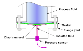 |
| Diagram of diaphragm seal (courtesy of Wikipedia) |
Sanitary processes, such as food and pharmaceuticals, use diaphragm seals to prevent against the accumulation of process fluid in pressure ports. If such a buildup were to occur, such as milk invading a pressure port on a pressure gauge and spoiling, the quality and purity of the fluid in the process may be compromised. Extremely pure process fluids, like ultra-pure water, could be contaminated by the metal surface of a process sensor. Pneumatic systems rely on the elimination of even the smallest pressure fluctuations, and diaphragm seals prevent those by ensuring the separation of the process materials from the sensors.
 |
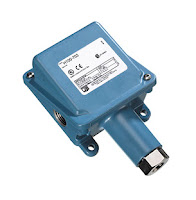
| Diaphragm seals protect the sensors on pressure switches like this United Electric Controls model. |
For more information on diaphragm seals, visit Ives Equipment at http://www.ivesequipment.com or call (877) 768-1600.
When It Comes to Pressure & Temperature Switches, Understand the Difference Between Switch Normal and Process Normal
 |
| Diagram of pressure switch. Note the SPDT electrical switch on top. (Courtesy of United Electric Controls) |
 |
| Temperature switch (courtesy of United Electric Controls) |
 |
| Pressure switch (courtesy of United Electric Controls) |
In making the connection between the normal state of switch contacts and the normal state of a process, one should relate the switch state to the process condition which would serve as the stimulus to change the switch state. For a limit switch, which responds to physical contact by an object, normal means the target is not contacting the switch. For a proximity switch, normal means the target is far away. A normal pressure switch condition occurs when the pressure is low, or may even indicate a vacuum. Level switches are normal when the level is empty. Normal for a temperature switch means the temperature is low. Flow switches are normal when there is a low flow rate, or the fluid is stopped. Both an understanding of normal as defined by the manufacturer of the switch and normal in terms of industry specific processes is necessary to correctly interpret the status of an operation. Once the concept of normal used in everyday conversation is uncoupled from your process control thinking, things fall into place easily.
Enhance Control System Security Using Process Switches
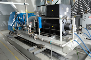 |
| Electro-mechanical switches do not have software or an operating system susceptible to cyber attack. |
Untied Electric Controls
This white paper looks at how open Microsoft technology used in virtually all contemporary control systems, such as distributed control systems (DCS) and supervisory control and data acquisition (SCADA), can mean less security. The paper explores why current solutions may not be up to the task of protection. It also shows how simple, yet reliable electro-mechanical switch-based protection can improve cyber defenses by complementing traditional techniques with another layer of protection independent of centralized control systems.
Better Technology, Less Security
A long running trend is behind the increasing vulnerability of control systems to hacking and other forms of cyber mischief. Centralized control systems are typically tied together through an open network and software that is susceptible to cyber-attack. What’s more, the network extends out beyond the plant floor. Indeed, a part of the plant floor network is increasingly reaching around the world, thanks to web-based tools and interfaces.
Networking adds extra capabilities, information sharing, and lowers the cost of commercial off-the-shelf components used in process control systems. Data from a control system can be fed into enterprise management software, enabling the use of business intelligence techniques to tackle problems and improve overall performance.
However, current networked systems are more vulnerable to attack than yesterday’s stand-alone and analog-based setups. This increased susceptibility arises from expanding exposure on two fronts. First, an open standardized network that can be accessed around the world for good can also be manipulated globally for bad. Second, the more complex a network becomes, in terms of connected devices and topology, the more likely it is that some vulnerability will open up, particularly if system updates are not deployed in a timely manner.
Perhaps the best known and most complete example of this in a SCADA setting is the Stuxnet worm, which was discovered in June 2010. Stuxnet infects computers through infected USB ash drives and exploits multiple Microsoft Windows security vulnerabilities. More recently, another worm related to Stuxnet dubbed Duqu was discovered by a Budapest University. Built on the same source code as Stuxnet, Duqu may be one of many malware worms floating in cyberspace ready to attack.
An investigation by the Idaho National Laboratory demonstrated potential physical damage with a 27-ton power generator by sending conflicting instructions governing speed and other characteristics that induced the generator to literally shake apart, destroying it. In a simulation, Sandia National Laboratory engineers showed that turning o a recirculation pump while upping heat could incapacitate an entire oil refinery by simply destroying a critical component.
Current Solutions Need Improvement
Traditional solutions are not as effective as they once were. One aspect of the traditional approach is to patch software to plug vulnerabilities. Doing this prevents an attacker from gaining control of a system through the use of a trick - such as a buffer overflow overloading the software – thereby allowing an attacker free reign.
Yet another approach is to employ firewalls and intrusion detection devices to keep intruders out and prevent the exploitation of weaknesses. Very sensitive and critical control applications are further hardened through network segregation to limit points of contact to the outside world, making the systems more secure. Costly redundant components and controllers can also be used, if control applications are vital enough to warrant the extra expense.
In today’s world, unfortunately, all of these tactics can – and do – fail due to the efforts of smart savvy attackers. On the software side, the list of vulnerabilities in Linux, Windows, iOS, Android and other operating systems is long and growing. Despite the valiant efforts of the control system suppliers, attacks can succeed if an un-patched operating system or applications exist inside a trusted area due to lax system upgrades.
In addition, the growth of newer technologies, such as fieldbus networks, industrial wireless networks, and mobile hand-held devices is another potential path for hackers. The new crop of safety instrumented systems (SIS) shift from separated analog systems to digital networking architectures may be susceptible to operating system weaknesses. Wireless networks are new and even with the extraordinary security measures included in the standards, only one entry point out of an infinite amount due to ubiquitous access points through sensors and mobile devices is needed to create havoc.
In total, this situation means that the most secure approach possible – network segregation – is much less effective.
Turning to Tried and True Technology
Clearly, there is a need to add to the defense against cyber-attack. Ideally, the defense would operate in the event of a compromised control system. The solution has to be fast acting, as even small delays can lead to damaged equipment, toxic environmental exposure, loss of life, and long downtimes. It also has to be reliable, working when needed and not triggering at the wrong times. Finally, it has to be hack-proof and support current infrastructure.
Electro-mechanical process switches, a robust and proven technology, meet all of these requirements. At first glance, this is somewhat surprising since the technology is not typically considered for cyber security. However, electro-mechanical switches do not have software or an operating system susceptible to cyber attack. When properly applied, electro-mechanical switches can provide safety functions independent of a central control system. There is no processor involved, which means there is nothing to hack. Electro-mechanical switches are also fast, tripping quickly when milliseconds count. What’s more, modern implementations, like United Electric’s 100, 120 and 400 Series
of pressure and temperature switches, have virtually no false positives. When these switches trip, it is because a safe operating limit has been exceeded, dangerous conditions exist, or both.
The key to this approach is the placement of switches so that they monitor suitable process parameters. They also must be connected so that they can take the appropriate action. In the event of an out-of-limit process condition, the switches will trip. Since the switches can power relays, they can be wired so as to shut down compressors, pumps, turbines or whatever is needed to correct the situation and limit the damage.
Of course, the choice of what parameters to measure and where to do so will be dictated by the particular process in question. Likewise, what to have a switch act upon will also be process specific. They could, for example, shut o a compressor to keep a vessel from an overpressure situation or they could trip relays to take an entire plant floor offline.
To see the power of this approach, consider that one of the first actions taken in Sandia National Laboratory oil refinery attack simulation was to put the system on manual, thereby overriding automated safeguards. This hack attempt would have failed, though, given an appropriately placed and configured electro-mechanical switch. The switch would have tripped once the temperature exceeded a set point. There would be nothing the attacker could have done.
As an added bonus, switches protect against both deliberate and accidental catastrophes. After all, they do not care why a temperature limit, for example, has been exceeded. The situation could be due to malicious hacking or the failure of a pump circulating coolant. In either case, though, the switch would take the same action and provide an emergency shutdown.
Conclusion
As has been shown, increasing connectivity and automation have brought bene ts, such as diagnostics, predictive maintenance, and process optimization to process control. However, by bridging the gap between control systems and the world, these advances have also made automated control systems vulnerable to attack. Traditional solutions may not be adequate to safeguard systems in an environment where multiple, rapidly evolving technologies combine to create many potential weak links.
The solution involves a properly designed safety layer of electro-mechanical process switches to complement traditional software solutions. Switches are fast, reliable, hack-proof, and act independent of the control system. Electro-mechanical switches should be considered as the primary or redundant layer to protect critical equipment in today’s dangerous landscape. So, while no control system today may be an island, electro-mechanical switches can, in effect, provide protection from intruders before they can cause damage.
An Introduction to Industrial Pressure, Differential Pressure, and Temperature Switches
 |
| Pressure switch with large diaphragm |
This post will provide a quick introduction of industrial electromechanical pressure switches and temperature switches.
An industrial pressure and temperature switch is made up of the three main components: 1) the sensor, 2) the housing and 3) the switching element.
The correct combination of each component assures proper application of the device for its intended use.
Sensor
The sensor is located above the pressure port and process connection. For pressure and differential pressure switches, there are several varieties of pressure sensors to choose. The most common types of pressure sensors are:
Metal Bellows - an accordion-like device that provides linear expansion and contraction based upon the application of pressure or vacuum. Bellows are excellent sensors because they provide good overall pressure range and are fairly sensitive to small changes in pressure.
Piston - A rod and o-ring combination that moves linearly in direct response to applied pressure. Piston sensors are normally only applied to only very high pressure ranges. They have very small surface areas and wide deadbands (the change in pressure required to change the position of the switch output).
 |
| Pressure switch with piston sensor |
Housing
Housings are classified and selected based on the atmosphere in which they’ll be used. Housing ratings are classified by several national and international agencies such as NEMA and CENELEC. Very generally put, housings can be rated as general purpose, dust & water resistant, water tight, corrosion resistant and hazardous (explosive) environments. Proper selection of the housing is important to the operation and life expectancy of the device. In hazardous environments, proper selection is absolutely critical. If unsure about the housing classification, consultation with an applications expert is required.
Switching Element
The switching element refers to the signaling device inside the enclosure that responds to the movement of the sensor. It can be either electrical or pneumatic, and provides an on-off signal (as opposed to an analog, or proportional signal produced by transmitters).
 |
| Differential pressure switch |
For the switching element and the sensor, it is very important to know the cycling rate (number of on vs. off times over a period of time) the instrument will see. Since both of these elements are mechanical, they will eventually wear out and need to be replaced. Switches are an economical and strong performing choice for low to medium cycle rates. For extremely high cycle rates, the use of solid state transmitters are a better choice.
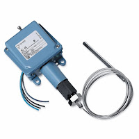 |
| Temperature switch |
An electromechanical temperature switch (sometimes called a thermostat) is, for the most part, a piston type pressure switch connected to an oil filled capillary and bulb sensing element. The thermal expansion of the oil inside the bulb and capillary creates the pressure and linear movement upon the piston sensor of the switch. The bulb and capillary elements can be supplied in copper or stainless steel, and at various lengths.
There are many more details to selecting and applying electromechanical pressure and temperature switches. This post is only intended to provide a very general introduction. It is always suggested to discuss your application with a qualified applications engineer so that you are assured to get the longest lasting, most economical and safest instrument possible.
Upgrading a Mechanical Pressure Switch to an Electronic (Solid State) Version
The example here uses the United Electric Controls One Series as the example.
This type of product (One Series) allows you to choose from explosion-proof, intrinsically safe and energy limited models that monitor gauge pressure, differential pressure or temperature. With up to two fully adjustable set points and deadbands, available 4-20 mA analog output, and absolutely no moving parts. They are used in a wide variety of applications where mechanical switches are not considered.


