Showing posts with label process instruments. Show all posts

Explosion-Proof ASIC or HART Pressure Transmitter

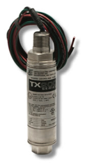
UE TX200
UE TX200
The TX200 is a compact, rugged pressure transmitter utilizing ASIC technology to provide optimum sensor signal conditioning and temperature compensation of the sensor output. It is designed for process control industries worldwide and ideally suited for petrochemical and upstream oil and gas applications. The TX200 provides a cost-effective solution to using conventional process transmitters.

The  fixed range model TX200B is recommended for use where process pressure is consistent within the range and where physical access to the transmitter is limited or not required.

The field adjustable model TX200A allows access to zero and span the transmitter. The transmitter may be spanned up to 5:1 and for ease of calibration, does not require a calibrated pressure source and can be calibrated in-place.

Both TX200 models feature an all welded, 316 stainless steel hermetically sealed enclosure providing airtight and watertight protection within the harshest environments. A 316 stainless steel, rotatable cover protects product markings and adjustment buttons (TX200A) from the elements and tampering. The TX200 lends itself to control panel mounting or direct process mounting due to its light-weight, cylindrical design.

TX200H Hart Models

The TX200H is a HART Smart pressure transmitter that provides simplified  eld adjustment while reliably communicating asset management data utilizing the latest HART 7 specification. A proprietary calibration process insures optimum temperature compensation limiting thermal effects on the sensor output. As with the ASIC TX200, it is suited for process control industries worldwide and provides a cost-effective solution to using conventional HART transmitters.

Download the PDF cut sheet for the UE TX200 from this link or read the embedded document below.

For more information on United Electric Controls products, contact Ives Equipment by calling (877) 768-1600 or by visiting https://ivesequipment.com.

Process Instrumentation White Paper: Seven Switch Myths Busted

One Series Pressure and Temperature Transmitter-Switches
One Series Pressure and Temperature
Transmitter-Switches (United Electric)
Summary

With more than 80 years of evolution since its introduction, switch technology as changed significantly enough that some of the common beliefs about switches are no longer true. Seven common myths surrounding switches are analyzed. Recent technology advancements in switch design and how these advancements solve problems in industrial and OEM applications are discussed. Readers will acquire a better understanding of the new technology available to improve control, process efficiency and safety.

1. Blind & Dumb

Prior generations of switches were incapable of displaying process measurements locally, forcing the installation of gauges that created more leak paths and added additional costs. Operators were unaware when installed switches stopped functioning due to welded contacts in the microswitch. Switches required removal from service and manual testing to conform functionality. Often, the control or safety function would go unprotected for days while the switch was in queue to be bench tested, creating an immediate safety concern.

These industry-wide problems inspired manufactures to innovate the next generation of switches that incorporate liquid crystal displays (LCD), presenting local process variable measurements, and integrated internal diagnostics, monitoring the health of the device. The addition of LCDs and device diagnostics increases up me and improves overall plant safety. Original equipment manufacturers (OEM) benefit from a reduction in installed components and a more dependable turnkey product for their customers.

2. Difficult Adjustments

Set point and deadband adjustments were a nuisance for operators and technicians. The instruments were required to be removed from service and calibrated on a bench in the maintenance shop. Installation instructions were not always available for installed devices, leading to wasted me searching for documentation or requesting additional information from the manufacturer. Delicate adjustments were required to achieve desired set points and deadbands, the dead time where no action happens, varied based on the microswitch inside the control. More often than not, instruments were mis- handled leading to premature failure due to inexperienced technicians.

Today’s generation of switches offer electronic platforms that reduce setup and programming to a ma er of seconds. A user interface on the local LCD provides simple prompts that allow users to program switch set points instantly without the need to remove the instrument from the process. Deadband and set point are now 100 percent adjustable, allowing operators to choose the desired range based on the application requirements. No longer are operators required to order and stock redundant devices in the event one failed in the eld. Users now have the flexibility of programming one switch to match many different process requirements.

3. Unsafe in Critical Applications - Not Appropriate for SIS

Industrial process plants are pushing pressure and temperature limits to new boundaries in an effort to stay competitive in a global market. Many of the systems designed 20 years ago were not intended to run at the current process extremes. It is only a ma er of me before these systems fail. Safety instrumented systems (SIS) are being installed to protect the process, people and the environment. These systems require devices that have been rigorously tested by third party agencies to verify the level of safety performance. Mechanical switches, referred to as sensors in SIS, are one of the most common components to fail in these systems. Users and designers require a switch that matches their required system performance level while also being fault tolerant.

Based on the strict performance requirements of SIS, newly introduced hybrid switches integrate the functionality of a switch and a transmitter. The switch portion of the device provides a direct digital output (relay output) to a final element that will instantly bring a process to a safe state in the event of a critically abnormal situation. The analog transmitter signal can be used for trending to determine the health of the device and the process. These new transmitter-switches and recently SIL 2 and 3 exida-certified devices (One Series Safety Transmitter) offer operators a simple and safe product that matches the demanding performance requirements of safety instrumented systems.

4. Problematic in Tough Environments

Whether installed on plant rotating equipment, such as turbines, or on demanding OEM auxiliary equipment, such as pumps or compressors, switches are required to function in tough environments that include shock, vibration, heat and pressure. Vibration is one of the leading causes of electro- mechanical switch failure. Most switches are mechanical in design and utilize a plunger to activate a microswitch. In areas of high shock and vibration, the plunger position can fluctuate and lead to false trips.

New solid-state, electronic switches provide a solution to the common problems with mechanical switches installed in high vibration applications. Because they have no moving parts, these switches can be mounted directly to the equipment or process without connecting impulse lines to keep them isolated from vibration. Industry leading turbine manufacturers and end users operating large compressors in petrochemical plants are experiencing much more reliability and fewer false trips with these new electronic switches, compared to the old mechanical designs.

5. Deploy Electromechanical Designs When Line Power is Unavailable

Most pressure switches sold over the past 80 years were designed to operate without electric power by incorpora ng a sensor that measures pressure by placing force on a plunger that would actuate a microswitch.

The first genera on of digital switches required line power to operate and were not adopted due the unavailability of line power and the cost of wiring. The new genera on of switches operates from leakage current in the circuit when connected to a host device, such as a Programmable Logic Controller (PLC), allowing electronic switches to be drop-in replacements for the old mechanical switches. Today, we have the ability to replace a blind and dumb mechanical switch with a new solid-state, electronic switch that offers a digital gauge, switch and transmitter in one instrument without adding any wiring or hardware.

6. Antiquated Technology


Today’s process plants run their processes faster and ho er than they were originally designed. Ultimately, these plants will have to ini ate modernization projects to support the new demands of the process. Old switches provided users with digital, on-off signals that were either wired to control a piece of equipment directly or sent to a PLC for alarm functionality. As plants go through modernization projects, they restructure control system input/outputs (I/O) to support more analog signals than the digital signals used in the past. Transmitters are commonly chosen and recommended over switches in these new projects, but transmitters do not provide the internal control functionality found in switches.

These modernization projects are costly requiring new equipment, updated wiring, expanded I/O, extensive engineering resources, and costly down me. Users are diligently exploring new ways to reduce overall project costs. The average process transmitter can cost upwards of $2,000 compared to the average process switch costing around $500. Process plants often have 100 to 1,000 switches installed. To upgrade all switches to transmitters could cost a plant up to $1.5 million. Consequently, switch manufacturers researched and developed new electronic switches that are capable of producing both digital and analog signals required by these new modernization projects, while keeping a similar price point to the original mechanical switches installed.

This dramatic savings allows plants to reduce the overall modernization project costs by upgrading the 2nd most likely component (sensor) to fail in a tradional safety system, without upgrading the rest of the safety system and reducing the down me needed to complete the project during a short shut- down turn- around project.

7. The Speed of Response of Transmitters is Faster than Switches


Without question, electromechanical switches are faster than any pressure transmitter on the market. With transmitters, huge amounts of conversions, computations, compensation, and other work must be done to get an accurate signal. Even using today’s high-speed processors, they cannot match the speed of the instantaneous reaction of a mechanical device. The fastest of these devices can be be er than 5 milliseconds while process transmitters can range from 300-500 milliseconds or more. Purpose built transmitters for safety applications designed for speed of response in lieu of accuracy (not needed in safety applications) can be as fast as 250 milliseconds. New solid state transmitter-switches can react in 100 milliseconds or less in the switch mode. If your application requires fast response such as in positive displacement (PD) pumps and turbine trip for over-speed protection, consider new solid-state transmitter-switches over process transmitters.

Recommendations


United Electric Controls has recognized the challenges faced by users and developed new products to match their growing needs. In an effort to reduce plant project costs and help OEMs design and build affordable and reliable equipment for the industrial sector, we have developed a new line of electronic switches that provide drop-in replacement of old mechanical switches. These new switches reduce the costs of plant modernizations. Built-in digital and analog communication provides users the op on of control- ling a piece of equipment locally or sending information back to a central control system for process trending and health, or both.

About this white paper:

UE ViewPoint white papers provide Executive, Business and Technical Briefs written by product, application and industry subject matter experts employed by United Electric Controls.  For more UE ViewPoint papers, visit this link.

Diaphragm Seals: Critical Isolation and Protection for Your Process Instruments

Diaphragm Seal
Diaphragm Seal courtesy of
AMETEK U.S. Gauge
Diaphragm seals play a critical role in protecting items like pressure switches, gauges, and transmitters from the fluid being evaluated by the sensor. The seal is a flexible membrane which both seals and isolates an enclosure. Pressure crosses the barrier without inhibition, but the material being contained does not. Typical materials composing diaphragm seals are elastomers, with rubbers being the prime substance in both general and specialty purposes.

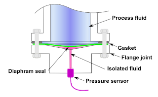
In the operating principle of the diaphragm seal, the chamber between the diaphragm and the instrument is filled with system fluid, allowing for the transfer of pressure from the process media to the sensor being protected. The seals are attached to the process by threaded, open flange, sanitary, or other forms of connection.  The seals can also be known as ‘chemical seals’ or ‘gauge guards’. Stainless steel, Carpenter 20, Hastelloy, Monel, Inconel, and titanium are used in high pressure environments, and some materials are known to work better when paired with certain chemicals.
Diagram of diaphragm seal
(courtesy of Wikipedia)

Sanitary processes, such as food and pharmaceuticals, use diaphragm seals to prevent against the accumulation of process fluid in pressure ports. If such a buildup were to occur, such as milk invading a pressure port on a pressure gauge and spoiling, the quality and purity of the fluid in the process may be compromised. Extremely pure process fluids, like ultra-pure water, could be contaminated by the metal surface of a process sensor. Pneumatic systems rely on the elimination of even the smallest pressure fluctuations, and diaphragm seals prevent those by ensuring the separation of the process materials from the sensors.

UE Pressure Switch
Diaphragm seals protect the sensors
on pressure switches like this
United Electric Controls model.
Despite their protective function and reliability, there are some potential complications related to diaphragm seals. Devices are now built to address and counter many potential issues related to process monitoring involving diaphragm seals. Products seek to eliminate any and all “dead space,” allow for continuous process flow, and are self-cleaning thanks to continuous flow design. Some high pressure seals come equipped with anti-clogging features, accomplished by the elimination of internal cavities while protecting gauges. Multi-purpose seals reduce temperature influence and improve instrument performance while pinpointing and diffusing areas of high stress. These pre-emptive measures result in longer instrument life-cycles and improve performance while ensuring protection from corrosion. The seals’ ability to protect both process quality and their own vitality make them essential components of process control.

For more information on diaphragm seals, visit Ives Equipment at http://www.ivesequipment.com or call (877) 768-1600.

Coriolis Flow Sensor with 15 RA/230 Grit for Sanitary Applications

Sanitary Coriolis flow sensor
with 15 RA / 230 Grit finish
on wetted parts.
(Courtesy of Siemens)
In sanitary applications, the finish and the material must be designed for easy and reliable cleaning and sanitation. For decades agencies have required sanitary finishes to comply to minimum standards. But now, many food, Biotech, and Pharma companies are going beyond the minimum regulations and providing high-end finishes because of the reduced sanitation time and reduced bacteria growth these finishes facilitate.

Sanitary applications mandate that stainless steel equipment have a sanitary finish. In very general terms, “sanitary finish” means a smooth, scratch-free, non-corrosive finish. But it’s much more than that. To qualify the finish more accurately, there are two primary terms used:

Roughness Average, or RA: A standard for an average of the peaks and valleys of the metal’s surface, measured in microinches or micrometers. The lower the RA, the smoother the finish.

Grit: The size of the abrasive used in the metal polishing process. Higher grit numbers are associated with higher polishing.

For process control equipment manufacturers, achieving higher-end finishes is not an easy proposition. Providing better finishes requires experience and controlled processes for quality fabrication, as well as possible tooling and production floor changes. Working inside sanitary requirements requires careful handling to prevent contamination from the manufacturing environment. Not all process instrument manufacturers are capable of providing the required environment.

A Coriolis Flowmeter with 15 RA/230 Grit for Biotech and Pharma

Siemens is currently offering a 15 RA/230 Grit surface finish for the FCS400 Coriolis flow sensor internal wetted-tube parts as a special, and will soon be offering it as a standard.

A Coriolis sensor, with such a high end finish, is very attractive to many "clean" industries including chromatography, blood plasma fractioning, chemical synthesis phases, Active Pharmaceutical Ingredient (API) extraction/fermentation and purification, formulation, and  purified API.

Biotech and Pharma manufacturers, in particular, are poised to take advantage of the enhanced 15 RA/230 Grit finish coupled with the inherent benefits of the FCS400 Coriolis flow sensor, namely:
  1. Accurate measurement across the entire range
  2. Zero internal fabrication joints and self-draining design
  3. All metal surfaces eliminate risks from particulates from the breakdown of synthetic materials
  4. No internal fluids to leak into the process
  5. A direct mass flow rate/ and total
For more information, contact:

Ives Equipment
www.ivesequipment.com
(877) 768-1600

Next Generation Tail Gas Analyzer

On-Line Process Analytics is a young industry. Now going into the 3rd generation, the paper below covers topics related to the specification, use and long term ownership of SRU process gas analyzers.


AMETEK Process Instruments has been the leader in tail gas analysis for over 40 years-with more than 1,100 installed model 880 NSL analyzers and more than 100 million hours of run time. The Model 888, the successor of the 880 NSL uses field-proven and highly reliable UV technology to accurately monitor the H2S and SO2 concentrations in sulfur recovery tail gas. This compact, rugged analyzer mounts directly on the process pipe, eliminating the complexity and safety issues of fiber optic coupled photometers.

The Model 888 is the evolution of a well proven formula. All the best elements of the iconic 880 NSL are still there; Four year lamp life, no shelter required and steam blow back for ammonia salts.

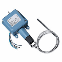
An Introduction to Industrial Pressure, Differential Pressure, and Temperature Switches

pressure switch
Pressure switch with large diaphragm
Most industrial applications require the monitoring of pressure and temperature of a process. Pressure and temperature measurement can be accomplished either by transmitters, gauges or by switches.
This post will provide a quick introduction of industrial electromechanical pressure switches and temperature switches.

An industrial pressure and temperature switch is made up of the three main components: 1) the sensor, 2) the housing and 3) the switching element.

The correct combination of each component assures proper application of the device for its intended use.

Sensor

The sensor is located above the pressure port and process connection. For pressure and differential pressure switches, there are several varieties of pressure sensors to choose.  The most common types of pressure sensors are:

Metal Bellows - an accordion-like device that provides linear expansion and contraction based upon the application of pressure or vacuum. Bellows are excellent sensors because they provide good overall pressure range and are fairly sensitive to small changes in pressure.

Piston - A rod and o-ring combination that moves linearly in direct response to applied pressure. Piston sensors are normally only applied to only very high pressure ranges. They have very small surface areas and wide deadbands (the change in pressure required to change the position of the switch output).

pressure switch
Pressure switch with piston sensor
Diaphragm - A thin, elastomer or metallic membrane, often with a rolled lip that allows for greater movement. The diaphragm has a large surface area and provides the most sensitivity to pressure change, making it ideal for low to mid-range pressure sensing.

Housing

Housings are classified and selected based on the atmosphere in which they’ll be used. Housing ratings are classified by several national and international agencies such as NEMA and CENELEC. Very generally put, housings can be rated as general purpose, dust & water resistant, water tight, corrosion resistant and hazardous (explosive) environments. Proper selection of the housing is important to the operation and life expectancy of the device. In hazardous environments, proper selection is absolutely critical. If unsure about the housing classification, consultation with an applications expert is required.

Switching Element

The switching element refers to the signaling device inside the enclosure that responds to the movement of the sensor. It can be either electrical or pneumatic, and provides an on-off signal (as opposed to an analog, or proportional signal produced by transmitters).

differential pressure switch
Differential pressure switch
The switching element is most times a “micro” type single pole, double throw (SPDT) electrical switch. These microswitches come in many configurations and electrical ratings, such as double pole, double throw (DPDT), 120/240 VAC, 12VDC, 24VDC, and hermetically sealed.

For the switching element and the sensor, it is very important to know the cycling rate (number of on vs. off times over a period of time) the instrument will see. Since both of these elements are mechanical, they will eventually wear out and need to be replaced. Switches are an economical and strong performing choice for low to medium cycle rates. For extremely high cycle rates, the use of solid state transmitters are a better choice.

temperature switch
Temperature switch
Temperature Switches

An electromechanical temperature switch (sometimes called a thermostat) is, for the most part, a piston type pressure switch connected to an oil filled capillary and bulb sensing element. The thermal expansion of the oil inside the bulb and capillary creates the pressure and linear movement upon the piston sensor of the switch. The bulb and capillary elements can be supplied in copper or stainless steel, and at various lengths.

There are many more details to selecting and applying electromechanical pressure and temperature switches. This post is only intended to provide a very general introduction. It is always suggested to discuss your application with a qualified applications engineer so that you are assured to get the longest lasting, most economical and safest instrument possible.

High-Temperature Capable Flammability Analyzer Increases Profit at Plastics Product Manufacturer

flammability analyzer
Flammability analyzer designed for
tough industrial applications
(courtesy of Control Instruments Corporation)
The customer is global supplier of vibration damping and sealing products for the automotive, consumer electronic and industrial markets that sells elastomer-coated metals, gaskets, brake shims and automotive and brake noise insulators. They also manufacture a variety of sealing materials, such as deck plates, oil filter adaptors, water outlets, pumps, relief valves, and rear cam and surge tank covers.

In their process solvents are applied to a web material. The web material contains PTFE and/ or rubber based adhesives and at times silicone. The main solvent component used is MEK which is not a high flash point solvent. Flammability analyzers were being used to monitor the flammability levels of the varying solvent levels in the zone’s atmosphere.

The flammability analyzers were mounted fairly far from the oven because of operating temperatures, and subsequently had long sampling lines. The last three zones were very challenging due to the distance and the use PTFE, silicones and other resins. Because the lines were so long, they were clogging from VOCs and vaporized web material and required the line to be shut down and cleaned. The downtime meant loss of production and loss of profits. The customer tried adding end-of-line filters on all sample tubing, which helped, but didn't solve the problem.

To solve the problem, the customer upgraded to a new flammability analyzer (a CIC model SNR674) rated for operating temperatures high enough (392 F) to keep all the elements in a vapor state and designed for use in a dirty environment. Theses new flammability analyzers are mounted directly on the oven wall eliminating the long sample lines. By keeping the sample lines as short as possible they were able to minimize the VOC condensation and eliminate the clogging.

For more information, contact:

Ives Equipment
(877) 768-1600
www.ivesequipment.com

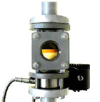
Level Phase Split Detection and Measurement

Phase Level Detection
Phase level detection.
Need a system for continuous interface measurement? This system will monitor the emission phase and detect when phase A/B occurs, avoiding any flow of the emulsion into the incorrect area. When phases are separated, the system allows for tight control, which increases efficiency of separation of liquids A&B.

This system provides the ability to remotely view a process that may not normally be watched. Multiple viewing stations may be linked to the system output so various departments may monitor a process. Customers may purchase video monitors, amplifiers or screen splitters to enhance the system.

 
  • Ethernet systems allow the additional functionality of being able to remotely view through a Gigabit network system. Users can have access to live system images from their office networked computer. 
  • Software is available for customers that require additional functionality over simple viewing of a live image. Liquid level, color of different phases, and visual verification. 
System verifies the color of fluid in phase split and sends an output signal locating specific points of the interface. All measurements can be recorded and archived for a historical record. 


Monitor phase split in batch mode on organic droplets for increased product recovery. As the droplets appear the system warns of organic phase and the upcoming emulsion. The amount of early droplets and their retraction time will indicate the completeness of the separation. Once the split is identified and stopped, the operator has a visual verification from the video monitor. The color can then be analyzed to ensure there is no inversion.

For more information, contact:

Ives Equipment
601 Croton Road
King of Prussia, PA 19406
(877) 768-1600
www.ivesequipment.com