 |
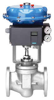
Valve positioner on
linear control valve
(Siemens SIPART) |
Industrial valves allow the flow of a process fluid through a pipe. Valves always include some type of actuation (opening/closing) device - from simple manual levers to sophisticated electric or pneumatic actuation packages. Industrial valves can act as on/off or proportioning devices to allow full flow, no flow, or modulated flow. When valves are used for modulating fluid flow, an instrument called a
valve positioner is installed.
A
valve positioner is used in tandem with a
valve actuator, the power source to open or close the valve. Positioners precisely direct the actuator to move the valve so that a desired flow volume is achieved and maintained. The positioner does this by monitoring the process condition, comparing it to a desired set point, and then pneumatically, electrically, or hydraulically manipulating the valve orifice until the difference between the set point and actual process variable is zero.
In closed loop control systems where the final control element are valves, valve positioners are the "brains" that provide the corrective signal to eliminate process offset. Positioners enable tighter control by overcoming the realities of valve wear, imprecise calibration, and a host of other process variable challenges.
Valve positioners are used throughout the process industries including power, pharmaceutical, chemicals, oil and gas, food and beverage, pulp and paper, refining and petrochemicals, pipelines, and many other processes.
Basic Function
 |
| Diagram of typical flow control loop using valve positioner. |
A valve positioner receives a signal from a controller. The controller could be part of a distributed control system (DCS), a programmable logic controller (PLC), or a discreet PID controller. The controller interprets a signal from some type of sensor, such as a flow transmitter, temperature transmitter, pressure transmitter, or other, and compares the transmitter reading to a desired setpoint. If the controller sees an offset (error), a corrective signal based on the difference, is sent to the valve positioner. The positioner then repositions the valve actuator that in turn readjusts the position of the valve, thereby changing the process condition, brining the system to to equilibrium.
Types of valve positioners:
Pneumatic Positioners
Pneumatic positioners receive pneumatic signals (3-15 or 6-30 PSIG) and proportion the supply air pressure to the valve actuator accordingly to move the valve to the required position. Pneumatic positioners are intrinsically safe and have the ability to provide a large amount of force to open or close a valve.
Electro-Pneumatic Positioners
Electro-pneumatic valve positioners are very similar to pneumatic postioners, except that they contain internal current-to-pneumatic converter (I/P). The current-to-pneumatic module receives a varying electrical signal (most commonly 4-20 mA) and converts that signal (proportionately) to a pneumatic output signal (3-15 PSIG or 6-30 PSIG). The pneumatic signal then then proportions the supply air pressure to the valve actuator.
Electric Positioners
Electric valve positioners receive an electric signal, usually 4-20 mA, 1-5 VDC, 2-10 VCD or 0-10 VDC and generally drive the motors in electric actuators. They perform the same function as pneumatic positioners do, but use electricity instead of air pressure as an input signal.
For more information on valve positioners, or any valve automation requirement, contact
Ives Equipment by visiting
https://ivesequipment.com or
calling 877-768-1600.


