Showing posts with label valve actuation. Show all posts

What Are Pneumatic Actuators?

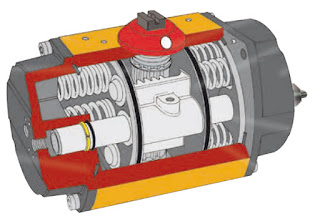
rack and pinion actuator
Internal view of rack and pinion actuator
(Flowserve Worcester)
Pneumatic valve actuators are used in extreme conditions in many industries such as oil and gas, chemical, water and wastewater, bulk storage, pulp & paper, and power generation. These devices are used in a multitude of valve control processes for regulation (or cessation) of flow, controlling pressure and adjusting level.  Due to their reliability and simplicity, pneumatic actuators are one of the most popular types of actuators used in industry today.

Pneumatic valve actuators work by conversion of air pressure into motion. The device applies a force of air to a diaphragm, rotary vane, or piston that is attached to the actuator shaft, which is then mechanically connected to the stem of the valve or damper. Depending on the type, pneumatic actuators produce either linear or rotary motion. 

ACTUATOR ACTION - SPRING RETURN OR DOUBLE ACTING

Spring Return — Pneumatic actuators with spring return design have air supplied from one side. The spring on the opposite side is responsible for the motion. With this design, air compression moves the opens or shuts the valves while the spring is responsible for the opposite motion. 

Double Acting  — Double acting actuators have air fed on both sides of a piston. The pressure on one side is higher as compared to the other that results in the required in movement. Air is used to open and close the valves.  
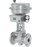
Diaphragm actuator
Diaphragm actuator
(Samson)
PNEUMATIC ACTUATOR DESIGNS

Diaphragm Actuators — Diaphragm actuators work by applying pressure to a thin membrane or diaphragm. 

Piston Actuators — Piston actuators apply compress air to a piston that is within a cylinder. Air is fed into a chamber that moves the piston in one direction. The piston moves in the opposite direction when air pressure is removed (spring assisted) or directed to the other side (double acting). 

Rack and Pinion — Rack and pinion actuators produce rotation by applying pressure to pistons with gears that turn a pinion gear. Rack and pinion actuators can be spring return or double acting. They are valued because of their compact size and versatility.

Scotch Yoke — A scotch-yoke actuator contains a piston, yoke, connecting shaft, and rotary pin.
Scotch yoke actuator
(Samson)
They can be direct acting or spring return. They are capable of providing very high torque outputs and are generally used on larger valves. Scotch yoke actuators can be powered by air or process gas.

Rotary Vane —Vane actuators use a mechanical vane, connected to a shaft, that separates a circular shaped body in two "clamshell" halves. The vane moves in response to the differential pressure inside the actuator body, turning the shaft clockwise or counter-clockwise in response to the pressure differential. External springs units are available for spring return models.

BENEFITS OF PNEUMATIC ACTUATORS

The use of compressed air (typically found in all industrial facilities) as the power source is the prime advantage for the use of pneumatic actuators. Additionally, pneumatic actuators have an advantage in suitability for different environments and can be used in extremes temperatures. They are preferred over electrical actuators in explosive, flammable and other hazardous areas because they do not require electricity (a possible ignition source) to operate. They do not create electrical fields or electrical noise since there is no electrical motor. Pneumatic valve actuators are faster opening and closing compared to their electric counterparts. Finally, they are low cost, lightweight, durable, require little maintenance (depending on quality) and there are a myriad of positioning controls, speed controls, and communications devices available for tailoring the actuator to the application.

DRAWBACKS OF PNEUMATIC ACTUATORS

While compressed air is the main reason for using pneumatic actuators, it can also be considered a drawback. For instance, pneumatic actuators can perform poorly when the air supply source is located at a distance, resulting in lag and slow response. Another drawback of pneumatic actuators is the additional cost for the compressed air system due to the requirement of dust filters and moisture removing dryers. These are required to ensure clean air is fed into the system.

APPLYING PNEUMATIC ACTUATORS

There are many aspects to the proper, safe, and efficient application of pneumatic actuators to valves and dampers. Sizing the power output (torque) being paramount. All valves and dampers have unique torque requirements. You must consider a threshold force for opening (breakaway), as the valve continues to move to its open or closed position, and then for seating. Matching the actuators to the valve type, and operating conditions is critical. Published torque curves must be reviewed and understood. Too little torque and the vale will not respond. Too much torque increases cost and can damage the valve. Spring return adds to this complexity. Considering all this, it is strongly suggested you always discuss any valve actuation requirement with an experienced applications expert. They will ensure the proper, safe, and cost effective mating of pneumatic actuator to valve or damper.

What Are Rack and Pinion Actuators?

Internal view of rack and pinion actuator
Operation rack and pinion actuator.
Rack and pinion actuators convert linear movement of a driving mechanism to provide a rotational movement designed to open and close quarter-turn valves such as ball, butterfly, or plug valves and also for operating industrial or commercial dampers.

There are three primary kinds of valve actuators are commonly used: pneumatic, hydraulic, and electric.

Pneumatic actuators can be further categorized as scotch yoke design, vane design, and the subject of this post - rack and pinion actuators.

How Rack and Pion Actuators Operate

Image courtesy of Wikipedia
The rotational movement of a rack and pinion actuator is accomplished via linear motion and two gears. A circular gear, known as a “pinion” engages the teeth of one or two linear gears, referred to as the “rack”.

Pneumatic actuators use pistons that are attached to the rack. As air or spring power is applied the to pistons, the rack changes position. This linear movement is transferred to the rotary pinion gear (in both directions) providing bi-directional rotation to open and close the connected valve.

Rack and pinion actuators pistons can be pressurized with air, gas, or oil to provide the linear the movement that drives the pinion gear. To rotate the pinion gear in the opposite direction, the air, gas, or oil must be redirected to the other side of the pistons, or use coil springs as the energy source for rotation. Rack and pinion actuators using springs are referred to as "spring-return actuators". Actuators that rely on opposite side pressurization of the rack are referred to as "direct acting".

Internal view of rack and pinion actuator
Most actuators are designed for 100-degree travel with clockwise and counterclockwise travel adjustment for open and closed positions. World standard ISO mounting pad are commonly available to provide ease and flexibility in direct valve installation.

NAMUR mounting dimensions on actuator pneumatic port connections and on actuator accessory holes and drive shaft are also common design features to make adding pilot valves and accessories more convenient.

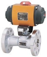
Rack and pinion actuator with valve
Rack and pinion
actuator with valve.
(Flowserve Worcester
Pneumatic pneumatic rack and pinion actuators are compact and effective. They are reliable, durable and provide good service life. There are many brands of rack and pinion actuators on the market, all with subtle differences in piston seals, shaft seals, spring design and body designs. Some variants are specially designed for very specific operational environments or circumstances.

Share your process valve control and automation challenges with application experts, and combine your process experience and knowledge with their product application expertise to develop effective solutions.

Definition: Industrial Valve Actuator

pneumatic actuator
Pneumatic actuator on ball valve.
(Worcester)
Actuators are devices which supply the force and motion to open and close valves. They can be manually, pneumatically, hydraulically, or electrically operated. In common industrial usage, the term actuator generally refers to a device which employs a non-human power source and can respond to a controlling signal. Handles and wheels, technically manual actuators, are not usually referred to as actuators. They do not provide the automation component characteristic of powered units.

electric actuator
Electric actuator (Worcester)
The primary function of a valve actuator is to set and hold the valve position in response to a process control signal. Actuator operation is related to the valve on which it is installed, not the process regulated by the valve. Thus a general purpose actuator may be used across a broad range of applications.

In a control loop, the controller has an input signal parameter, registered from the process, and compares it to a desired setpoint parameter. The controller adjusts its output to eliminate the difference between the process setpoint and process measured condition. The output signal then drives some control element, in this case the actuator, so that the error between setpoint and actual conditions is reduced. The output signal from the controller serves as the input signal to the actuator, resulting in a repositioning of the valve trim to increase or decrease the fluid flow through the valve.

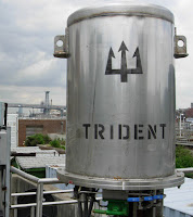
electro-hydraulic actuator
Electro-hydraulic actuator
(MIH Trident)
An actuator must provide sufficient force to open and close its companion valve. The size or power of the actuator must match the operating and torque requirements of the companion valve. After an evaluation is done for the specific application, it may be found that other things must be accommodated by the actuator, such as dynamic fluid properties of the process or the seating and unseating properties of the valve. It is important that each specific application be evaluated to develop a carefully matched valve and actuator for the process.

Hydraulic and electric actuators are readily available in multi-turn and quarter-turn configurations. Pneumatic actuators are generally one of two types applied to quarter-turn valves: scotch-yoke and rack and pinion. A third type of pneumatic actuator, the vane actuator, is also available.

For converting input power into torque, electric actuators use motors and gear boxes while pneumatic actuators use air cylinders. Depending on torque and force required by the valve, the motor horsepower, gearing, and size of pneumatic cylinder may change.

There are almost countless valve actuator variants available in the industrial marketplace. Many are tailored for very narrow application ranges, while others are more generally applied. Special designs can offer more complex operating characteristics. Ultimately, when applying actuators to any type of device, consultation with an application specialist is recommended to help establish and attain proper performance, safety and cost goals, as well as evaluation and matching of the proper actuator to the valve operation requirements. Share your fluid process control requirements with a specialist in valve automation, combining your own process knowledge and experience with their product application expertise to develop effective solutions.

Contact Ives Equipment for any valve actuator application. Visit http://www.ivesequipment.com or call (877) 768-1600.

New Ives Equipment Video

Ives Equipment, founded in 1954, provides a diverse range of process control equipment, including valves, regulators, wireless products, flow products, pressure gauges, control products, level instrumentation, sanitary products, temperature instruments, analytical products, electric heat trace and bio-pharmaceutical products.

For more than 60 years, Ives Equipment Corporation has successfully served the industries of eastern and central Pennsylvania, Delaware, Maryland, metro NY, New Jersey, Virginia and Washington DC with the latest in process control equipment and services.

The Ives business is built on a foundation of quality people, highly trained and experienced, who take a keen interest in finding the optimum solutions to customers' control problems.

Industrial Control Valve Actuator Operating Principles

Control valve actuators control fluid in a pipe by varying the orifice size through which the fluid flows. Control valves contain two major components, the valve body and the valve actuator. The valve body provides the fluid connections and immovable restrictor comprised a valve stem and plug that is in contact with the fluid that varies the flow.

The valve actuator is the component that physically moves the restrictor to vary the fluid flow. Three actuator types are used in control valves and they include spring and diaphragm, solenoid, and motor. As the name suggests the spring in diaphragm actuator uses a spring and a diaphragm to move the valve stem and plug.

A 15 PSI pneumatic signal enters the housing at the top of the actuator. As pressure is exerted on the diaphragm a downward force is applied against the spring which moves the restrictor. The diaphragm moves until it creates an equal but opposing force against the spring at which time the motion stops as the plug meets the valve seat. With no air pressure the restrictor is pushed upward by the spring to act as a normally open control valve. To vary the position of the restrictor and flow through the valve, a current to pressure transducer can be used to provide a three to 15 PSI signal to the diaphragm.  At 3 PSI the valve is maintained open, and 15 PSI the valve is maintained closed. Pressures between the three to 15 PSI range proportionally change the flow of the valve. For example a pressure of 9 PSI applied to the diaphragm moves the spring and valve stem to 50 percent operating range.

For on /off control of the valve, a solenoid is used to actuate the valve to a fully closed or fully open position. Applying current to the coil generates a magnetic field that moves the plunger downward against the return spring. With zero current applied to the coil the spring pulls the plunger upwards to the fully open position for a normally open state control valve.

Another method for variable valve positioning uses a motor and is referred to as proportional control mode. Using a gear motor attached to the valve stem a servo amplifier provides a DC control signal that moves the valve to the desired position. Feedback is achieved with the wiper arm attached to the valve stem that sends a signal back to the servo amplifier where the position is monitored the servo amplifier drives the motor until the control signal is equal to the feedback signal.

Watch the video below for an illustrated explanation. For more information on control valves, contact Ives Equipment at 877-768-1600 or visit http://www.ivesequipment.com.

Introduction to Electrically Actuated Valves (Motor Operated Valve or MOVs)

electric valve actuators
Electric valve actuators for MOVs
The two most common methods of opening and closing industrial valves are by pneumatic actuators and electric actuators. This video introduces the viewer to electric valve operation.

Commonly known as "motor operated valves", or MOVs, electric operators can be fitted to any quarter-turn valve (90 deg. rotation) (such as a ball, butterfly or plug valve), or linear movement valve (such as a globe or gate valve).

Most often electric actuators are used where electric power is readily available and a pneumatic air systems are not. They are available in a variety of voltages and torque outputs for various size valves. Accessories such as limit switches, positioners, and hazardous area enclosures are available as well.