"We hold these truths to be self-evident, that all men are created equal, that they are endowed by their Creator with certain unalienable Rights, that among these are Life, Liberty and the pursuit of Happiness. — That to secure these rights, Governments are instituted among Men, deriving their just powers from the consent of the governed, — That whenever any Form of Government becomes destructive of these ends, it is the Right of the People to alter or to abolish it, and to institute new Government, laying its foundation on such principles and organizing its powers in such form, as to them shall seem most likely to effect their Safety and Happiness."
THOMAS JEFFERSON, Declaration of Independence
Educational information on process control, industrial instrumentation, valves, valve automation and control valves. For additional information visit IvesEquipment.com or call 877-768-1600
Refinery Gas Analyses Using Compact Gas Chromatographs and Gas Detectors
The analysis of trace permanent gases has many different fields of application in the petrochemical industry. One of the most important is for controlling the manufacturing process and the product quality. For example, some contaminants as carbon monoxide and carbon dioxide tend to deteriorate the catalysts in the propylene and ethylene polymer grade production.
An instrument for monitoring trace impurities is then required. Many different GC techniques are available on the market. Most of the techniques use a combination of TCD, FID and methanizer for the trace analysis of H2-O2-N2-CH4-CO-CO2 in propylene and ethylene. More precisely, an FID and a methanizer are used to trace CH4-CO and CO2. A TCD with Hydrogen or Helium carrier gas is used to trace O2-N2 detection. Finally, a second TCD with Argon or Nitrogen carrier gas must be added to trace H2 detection. These solutions require complex GC solutions with multiple detectors and multiple gas sources for carrier, fuel and air. On top of that, an FPD must be added in some cases when the trace analysis of H2S is required.
Read the application note below for more information. Contact Ives Equipment at (877) 768-1600 or visit http://www.ivesequipment.com for a consultation.
Labels:
Delaware,
Gas Chromatograph,
gas detection,
Gas Detector,
LDetek,
Maryland,
New Jersey,
New York,
Pennsylvania,
refinery,
Virginia
Understanding Hydrostatic Pressure
Pressure measurement is an inferential way to determine the height of a column of liquid in a vessel in process control. The vertical height of the fluid is directly proportional to the pressure at the bottom of the column, meaning the amount of pressure at the bottom of the column, due to gravity, relies on a constant to indicate a measurement. Regardless of whether the vessel is shaped like a funnel, a tube, a rectangle, or a concave polygon, the relationship between the height of the column and the accumulated fluid pressure is constant. Weight density depends on the liquid being measured, but the same method is used to determine the pressure.
A common method for measuring hydrostatic pressure is a simple gauge. The gauge is installed at the bottom of a vessel containing a column of liquid and returns a measurement in force per unit area units, such as PSI. Gauges can also be calibrated to return measurement in units representing the height of liquid since the linear relationship between the liquid height and the pressure. The particular density of a liquid allows for a calculation of specific gravity, which expresses how dense the liquid is when compared to water. Calculating the level or depth of a column of milk in a food and beverage industry storage vessel requires the hydrostatic pressure and the density of the milk. With these values, along with some constants, the depth of the liquid can be calculated.
The liquid depth measurement can be combined with known dimensions of the holding vessel to calculate the volume of liquid in the container. One measurement is made and combined with a host of constants to determine liquid volume. The density of the liquid must be constant in order for this method to be effective. Density variation would render the hydrostatic pressure measurement unreliable, so the method is best applied to operations where the liquid density is known and constant.
Interestingly, changes in liquid density will have no effect on measurement of liquid mass as opposed to volume as long as the area of the vessel being used to store the liquid remains constant. If a liquid inside a vessel that’s partially full were to experience a temperature increase, resulting in an expansion of volume with correspondingly lower density, the transmitter will be able to still calculate the exact mass of the liquid since the increase in the physical amount of liquid is proportional to a decrease in the liquid’s density. The intersecting relationships between the process variables in hydrostatic pressure measurement demonstrate both the flexibility of process instrumentation and how consistently reliable measurements depend on a number of process related factors.
For more information on any type of pressure instrumentation, visit Ives Equipment at http://www.ivesequipment.com or call 877-768-1600.
Labels:
Delaware,
gauge,
Hydrostatic Pressure,
Maryland,
New Jersey,
New York,
Pennsylvania,
pressure switch,
Virginia
An Explanation of Industrial Process Heating Technologies
 |
| Boiler providing steam for process heat. |
Fuel-based process heating systems generate heat by combusting solid, liquid, or gaseous fuels, then transferring the heat directly or indirectly to the material. Hot combustion gases are either placed in direct contact with the material (i.e., direct heating via convection) or routed through radiant burner tubes or panels that rely on radiant heat transfer to keep the gases separate from the material (i.e., indirect heating). Examples of fuel-based process heating equipment include furnaces, ovens, red heaters, kilns, melters, and high-temperature generators.
Steam-based process heating systems introduce steam to the process either directly (e.g., steam sparging) or indirectly through a heat transfer mechanism. Large quantities of latent heat from steam can be transferred efficiently at a constant temperature, useful for many process heating applications. Steam-based systems are predominantly used by industries that have a heat supply at or below about 400°F and access to low-cost fuel or byproducts for use in generating the steam. Cogeneration (simultaneous production of steam and electrical power) systems also commonly use steam-based heating systems. Examples of steam-based process heating technologies include boilers, steam spargers, steam-heated dryers, water or slurry heaters, and fluid heating systems.
Electricity-based process heating systems also transform materials through direct and indirect processes. For example, electric current is applied directly to suitable materials to achieve direct resistance heating; alternatively, high-frequency energy can be inductively coupled to suitable materials to achieve indirect heating. Electricity-based process heating systems are used for heating, drying, curing, melting, and forming. Examples of electricity-based process heating technologies include electric arc furnace technology, infrared radiation, induction heating, radio frequency drying, laser heating, and microwave processing.
Hybrid process heating systems utilize a combination of process heating technologies based on different energy sources and/or heating principles to optimize energy performance and increase overall thermal efficiency. For example, a hybrid boiler system may combine a fuel-based boiler with an electric boiler to take advantage of access to lower off-peak electricity prices. In an example of a hybrid drying system, electromagnetic energy (e.g., microwave or radio frequency) may be combined with convective hot air to accelerate drying processes; selectively targeting moisture with the penetrating electromagnetic energy can improve the speed, efficiency, and product quality as compared to a drying process based solely on convection, which can be rate-limited by the thermal conductivity of the material. Optimizing the heat transfer mechanisms in hybrid systems offers a significant opportunity to reduce energy consumption, increase speed/throughput, and improve product quality.
Hybrid process heating systems utilize a combination of process heating technologies based on different energy sources and/or heating principles to optimize energy performance and increase overall thermal efficiency. For example, a hybrid boiler system may combine a fuel-based boiler with an electric boiler to take advantage of access to lower off-peak electricity prices. In an example of a hybrid drying system, electromagnetic energy (e.g., microwave or radio frequency) may be combined with convective hot air to accelerate drying processes; selectively targeting moisture with the penetrating electromagnetic energy can improve the speed, efficiency, and product quality as compared to a drying process based solely on convection, which can be rate-limited by the thermal conductivity of the material. Optimizing the heat transfer mechanisms in hybrid systems offers a significant opportunity to reduce energy consumption, increase speed/throughput, and improve product quality.
For more information, visit www.ivesequipment.com or call (877) 768-1600.
An Industrial Valve Positioner that Offers Decisive Advantages
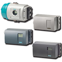
The SIPART ® PS2 electro-pneumatic valve positioner is used to control the final control element of pneumatic linear or part-turn valve actuators. The electro-pneumatic valve positioner moves the actuator to a valve position corresponding to the setpoint. Additional function inputs can be used to block the valve or to set a safety position. A binary input is present as standard in the basic device for this purpose.
The SIPART PS2 smart valve positioner is characterized by significant advantages compared to conventional devices, such as:
The SIPART PS2 smart valve positioner is characterized by significant advantages compared to conventional devices, such as:
- Only one device version for linear and part-turn valve actuators
- Simple operation and programming using three keys and a two-line LCD
- Automatic startup function with self-adjustment of zero and span
- Manual operation without additional equipment
- Selectable or freely-programmable characteristics
- Minimum air consumption
- Selectable setpoint and manipulated variable limiting
- Programmable "tight shut-off function"
Labels:
control valve,
Delaware,
Maryland,
New Jersey,
New York,
Pennsylvania,
positioner,
Siemens,
SIPART,
valve automation,
Virginia
Upgrading to a United Electric (UE) Controls One Series from a Mechanical Pressure Switch
 This video below demonstrates how to replace an older on/off mechanical pressure switch and install the UE One Series.
The One Series electronic pressure and temperature transmitter-switches set the standard for smart digital process monitoring. With a fully adjustable set point and deadband and 0.1% repeatability, the One Series performs in a wide variety of applications. Available in Type 4X enclosures approved for intrinsic safety, flameproof and non-incendive area classifications, these hybrid transmitter-switches are designed to provide transmitter, switch and gauge functions all-in-one rugged enclosure that can withstand the rigors of harsh and hazardous environments.
Each One Series model incorporates intelligent self-diagnostics and can report detected faults before they become major safety issues. Plug Port Detection protects against sensor clogging. Nuisance trip filtering reduces false and spurious signals. The ability to capture pressure spikes and valleys provides process information to aid in the commissioning and debugging process.
For more information, visit http://www.ivesequipment.com or call (877) 768-1600.
Remote Telemetry Outstation / Data Logger for Water Utilities
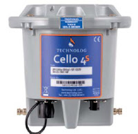 |
| Technolog Cello 4S data logger. |
The Cello 4S can have up to two pressure, eight user programmable digital or analogue inputs and two individually switched 12 Volt outputs for powering 4-20mA loops. Setup is made easy through an optional WiFi communication interface, and remote set-up, monitoring and control is facilitated through locally deployed PMAC software or web based WaterCore platform.
 |
| Technolog Cello 4S installed. |
The Cello 4S provides closed loop control of pressure reducing valves, pressure sustaining valves and variable speed pumps, high accuracy battery monitoring for optimal asset management, is housed in a sturdy, portable, and waterproof to IP68 enclosure, offers 5 year battery life (typically) and includes water temperature measurement.
Or, view the specification sheet below:
Labels:
Cello 4S,
data logger,
Delaware,
Maryland,
New Jersey,
New York,
Pennsylvania,
Technolog,
Virginia,
water
Advanced Safety Integrity Universal Gas Transmitter
The Sensidyne SensAlert ASI provides enhanced protection and dependability for critical safety applications where personnel, processes, and facilities are at risk. The third-party certified SIL-2 SensAlert ASI offers dependability and versatility while remaining the easiest to install, commission, operate, and maintain.
SensAlert ASI is third-party certified to IEC61508 Level 2 (SIL-2) for both hardware and software with certification to global hazardous area and performance standards. The Test-on-Demand feature with on-board gas generator provides remote functionality checks with generated gas while Predictive Sensor End-of-Life Indication provides advanced warning of impending sensor failure.
SensAlert ASI is third-party certified to IEC61508 Level 2 (SIL-2) for both hardware and software with certification to global hazardous area and performance standards. The Test-on-Demand feature with on-board gas generator provides remote functionality checks with generated gas while Predictive Sensor End-of-Life Indication provides advanced warning of impending sensor failure.
For your convenience, we have posted the SensAlert ASI Users Manual below.
Labels:
ASI,
Delaware,
gas detection,
Maryland,
New Jersey,
New York,
Pennsylvania,
Process Control,
safety,
Sensidyne,
Virginia
Vibrating Point Level Switch Operating Principles and Use
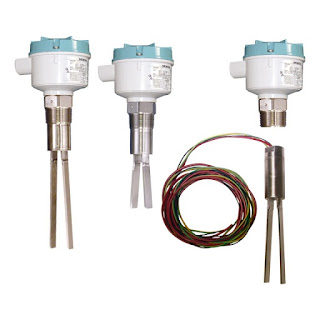 |
| Vibrating point level switches (SIEMENS) |
The operating principle of the vibrating fork is based on the oscillating fork resonating at a known frequency in air when it is set in motion. Upon contacting a medium other than air, the resonant frequency is shifted, depending on the medium contacting or immersing the fork. Typically, fork-type level switches are installed on either the side or the top of a liquid process tank. An exciter keeps the fork oscillating, and a detector circuit monitors fork vibrating frequency, providing a change in the output signal when the frequency changes. Contact or immersion of the fork in liquid will change the fork vibrating frequency sufficiently to produce a change in output signal. Depending on the configuration of the level switch, it can function as a liquid level alarm, or provide a control output for a pump, valve, or other device. Sensor response, the change in fork vibration frequency, is a function of liquid density. Liquids with greater density will generally produce a larger frequency shift in the vibrating fork.
The wide use of vibrating level switches across various process industries is a testament to the reliability of the technology. The devices protect against overfill, indicate high and low points inside tanks, and are useful over a wide range of temperatures. A sturdy design, coupled with product variants that include a variety of sensor materials, selectable probe length, and specialized output features make vibrating fork switches applicable in many operations where level indication is needed. Chemical processing, mining, food and beverage, plastics, and other industries utilize the switches, thanks to their customizable designs and consistent performance. An advantage offered by vibrating fork level switches is a resistance to factors that sometimes confound other technologies employed for level indication. The devices will reliably function despite flow, bubbles, foam, vibration, and coating complexities related to the subject liquids. Additionally, vibrating fork switches are reliable in both high level and low level indication scenarios.
Highly viscous liquids are generally not good candidates for the application of a vibrating fork level switch. Some liquids present the potential for material accumulation between the forks, possibly resulting in poor performance. Both of these limitations are addressed by various design features incorporated by different manufacturers.
The SIEMENS SITRANS LVS200 is a vibrating point level switch for high or low levels of bulk solids. The standard LVS200 detects high, low or demand levels of dry bulk solids in bins, silos or hoppers. The liquid/solid interface version can also detect settled solids within liquids or solids within confined spaces such as feed pipes. It is designed to ignore liquids in order to detect the interface between a solid and a liquid. Additionally, the SITRANS LVS200 has an optional 4 to 20 mA output for monitoring buildup on the fork to determine when preventative maintenance should be performed in sticky applications.
For more information on any level sensing application, contact Ives Equipment by visiting http://www.ivesequipment.com of calling 877-768-1600.
The Ten Things Everyone Should Know about pH and ORP
Reprinted with permission from AquaMetrix Instruments
Here is a list of the ten things anyone in the business of measuring the pH or ORP of their process should know that will make his or her job more stress-free.
1. pH measurements are only good to 0.1 pH units.
Electrodes are funny things. They are the only electronic components that don’t even have specifications listed in their data sheets. One major figure of merit, the impedance of the glass electrode, is on the order of megaohms and can vary by a factor of two. Cross sensitivity to other ions (e.g. sodium), response time and differences between any two electrodes limit the accuracy of measurement. Expecting ac- curacy of greater than 0.1 pH units is
2. Speaking of accuracy... It is not the same as precision.
For a consistent process a pH probe can achieve precision of results to within 0.02 units but it’s accuracy will always be limited by variables such as calibration accuracy, high sodium content or careful routine calibration, however, will narrow the gap between the accuracy of readings closer to the lower level of precision.
3. ORP measurements are only good to ± 20 mV.
Once again the measurement of ORP might be characterized by a high precision but the accuracy of the reading is constrained by the dif culty of calibration, as explained in point 6, and the non-buffered calibration solutions that allow the ORP value of the calibration solutions to change over time. Whereas the buffered composition of pH calibration solutions insures that they will change minimally an ORP calibrations solution is a mixture of Fe2+ and Fe3+ salts. Just the addition of air to the mixture will increase the ORP of the mixture. So don’t look for “NIST traceable” on the label of an ORP calibration solution.
4. ORP measurements are relative.
The process electrode is nothing more than a platinum (or gold) band upon which oxidation (reduction) reactions take place. To complete the circuit, as in all potentiometric devices, is a
reference electrode. Usually that is the same Ag/AgCl electrode used in a pH probe so the REDOX potential that you read is the difference between the Pt band process electrode and the arbitrarily chosen reference electrode. What matters most with an ORP measurement is its change to an agreed upon standard.
5. pH calibration requires two points.
Calibration measures the response of an instrument as one changes the measurement variable in a known way. For pH measurements that measurement variable is the concentration of hydrogen ions. One calibrates a pH probe by drawing a line through points representing the response of a pH probe to more than one H+ ion concentrations (or pH values). Therefore calibration requires at least two points.
6. ORP calibration can only realistically be done with one point.
This sounds like a reversal of point 4 but it’s not. ORP is not a measure of any one species (e.g. H+ ions or oxygen molecules). It measures the collective REDOX potential of everything in the water. Furthermore calibration solutions, e.g. 200 mV Light’s solution and 600 mV Zobell’s solution are two completely different mixtures of reagents. Therefore all we can is choose one calibration solution and calibrate for it.
7. ORP measurements can be slow.
Stick an ORP probe in a calibration solution and you will get a steady reading with- in half a minute. Take the same probe and stick it in a glass of tap water and it might take 20 minutes for the reading to settle to the 200-300 mV that is typical of tap water. The response of the process electrodes to the REDOX reactions that take place on the surface of a Pt electrode depends on the speed of the many reactions that give the potential and the rate at which molecules diffuse through the water. The Fe2+ and Fe 3+ ions that comprise most of the ORP value in calibration solutions react very quickly with the Pt but the Cl- and dissolved oxygen that make up tap water react much more slowly. So the key to successful ORP measurement is patience.
8. pH measurements must be temperature compensated to be accurate.
A pH measurement is the determination of H+ ions in solution. Higher temperature causes the chemical activity to increase and the pH reading to increase accordingly. So we must remove the temperature effect by measuring it and using the well known Nernst equation to correct it for the reading at 250C. (The correction is quite simple. The pH value is proportional to temperature when the latter is an absolute value (i.e. in Kelvins).
9. ORP measurements are affected by temperature but are NOT corrected for it.
An ORP value simply reflects the ability of whatever is in the water to oxidize whatever contaminants are in the water. Of course oxidation speeds up at higher temperatures. But since ORP measures the rate of chemical reactions and not any one chemical species there is no need to correct it. However we can convert the temperature reading to the ORP that we would measure at 250 C so that we have a basis for comparing the chemistry of the process. That’s why we provide a temperature sensing thermistor or RTD with our differential ORP probes.
10. A differential probe properly cared for will last a long time but it won’t last forever.
Over time chemicals in the process make their way through the junction or salt bridge and into the pH 7 buffer that bathes the reference electrode. Manufacturers go to great length to minimize this contamination but they can only slow it down. Aquametrix differential probes allow the user to cheaply and quickly replenish both the pH 7 solution and the salt bridge so that our probes our industry leaders when it comes to probe lifetime. Nonetheless electrodes themselves lose their efficiency as the glass becomes contaminated and/or eroded by the process. However the good news that, with routine calibration and maintenance an Aquametrix differential probe can last for years in most environments. As the car ads say, “your mileage will vary” but rest assured there is no probe on the market that will outlast an Aquametrix differential probe... as long as you take good care of it.
Over time chemicals in the process make their way through the junction or salt bridge and into the pH 7 buffer that bathes the reference electrode. Manufacturers go to great length to minimize this contamination but they can only slow it down. Aquametrix differential probes allow the user to cheaply and quickly replenish both the pH 7 solution and the salt bridge so that our probes our industry leaders when it comes to probe lifetime. Nonetheless electrodes themselves lose their efficiency as the glass becomes contaminated and/or eroded by the process. However the good news that, with routine calibration and maintenance an Aquametrix differential probe can last for years in most environments. As the car ads say, “your mileage will vary” but rest assured there is no probe on the market that will outlast an Aquametrix differential probe... as long as you take good care of it.
Labels:
analytics,
AquaMetrix,
Delaware,
Maryland,
New Jersey,
New York,
ORP,
Pennsylvania,
pH,
Virginia,
water quality,
water treatment
Diaphragm Seals: Critical Isolation and Protection for Your Process Instruments
 |
| Diaphragm Seal courtesy of AMETEK U.S. Gauge |
In the operating principle of the diaphragm seal, the chamber between the diaphragm and the instrument is filled with system fluid, allowing for the transfer of pressure from the process media to the sensor being protected. The seals are attached to the process by threaded, open flange, sanitary, or other forms of connection. The seals can also be known as ‘chemical seals’ or ‘gauge guards’. Stainless steel, Carpenter 20, Hastelloy, Monel, Inconel, and titanium are used in high pressure environments, and some materials are known to work better when paired with certain chemicals.
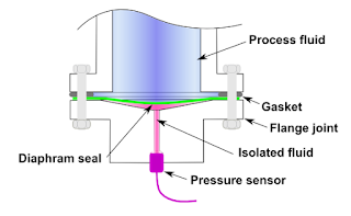 |
| Diagram of diaphragm seal (courtesy of Wikipedia) |
Sanitary processes, such as food and pharmaceuticals, use diaphragm seals to prevent against the accumulation of process fluid in pressure ports. If such a buildup were to occur, such as milk invading a pressure port on a pressure gauge and spoiling, the quality and purity of the fluid in the process may be compromised. Extremely pure process fluids, like ultra-pure water, could be contaminated by the metal surface of a process sensor. Pneumatic systems rely on the elimination of even the smallest pressure fluctuations, and diaphragm seals prevent those by ensuring the separation of the process materials from the sensors.
 |
| Diaphragm seals protect the sensors on pressure switches like this United Electric Controls model. |
For more information on diaphragm seals, visit Ives Equipment at http://www.ivesequipment.com or call (877) 768-1600.
Introduction to Flowmeters
 |
| Magnetic flowmeters (courtesy of Siemens) |
 |
| Turbine flow meter internal view (courtesy of Niagara) |
Because they are needed for a variety of uses and industries, there are multiple types of flowmeters classified generally into four main groups: mechanical, inferential, electrical, and other.
 |
| Variable Area Flowmeters (courtesy of Siemens) |
Quantity meters, more commonly known as positive displacement meters, mass flowmeters, and fixed restriction variable head type flowmeters all fall beneath the mechanical category. Fixed restriction variable head type flowmeters use different sensors and tubes, such as orifice plates, flow nozzles, and venturi and pitot tubes.
Inferential flowmeters include turbine and target flowmeters, as well as variable area flowmeters also known as rotameters.
Laser doppler anemometers, ultrasonic flowmeters, and electromagnetic flowmeters are all electrical-type flowmeters.
For any flowmeter application or question, visit Ives Equipment at www.ivesequipment.com or call (877) 768-1600.
Labels:
Delaware,
flowmeter,
Maryland,
New Jersey,
New York,
Niagara,
Pennsylvania,
Siemens,
Virginia
Instrumentation and Controls for the Grain Industry
 |
| Instruments and control for grain producers. |
A successful grain merchant during the 1840s is considering expansion in the coming years. Recent years have been fruitful, but there are rumors of a new invention on the market: a grain elevator. Claims are that this elevator is able to unload more than 1,000 bushels each hour! Compare this to current operations where workers carry sacks of grain on their backs from wagons to waiting ships. Our grain merchant has seen firsthand the hazards of this process – everything from suffocating and explosive grain dust to the daily stresses on workers’ bodies. Will this new technology be able to increase the merchant’s profits as well as make a safer working environment for employees?
Over a century and a half later, mechanized equipment is now an essential part of the grain industry, from planting and growing to harvesting, handling, and milling grain. Your challenges are still the same as those of nineteenth century grain operators, though – how can you improve processes and cut costs while also increasing safety?
Tracking inventory in grain silos is a significant component of a successful grain operation. Managing raw materials and finished products is essential for keeping processes efficient and optimizing inventory ordering and shipments. By knowing where materials are located, companies can use these resources more effectively, decreasing human intervention and increasing efficiency. As well, checking bin levels on a regular basis requires substantial labor costs. To make inventory track-ing faster and more streamlined, the industry is continually moving towards automated inventory management.
Promoting a culture of safety
Working with grain has the potential to be deadly, especially when grain is in motion. Similar to ‘quicksand,’ moving grain can bury a worker in seconds. In 2010, U.S. grain operators reported that fifty-one workers had been trapped in grain, more than in any year since Purdue University began collecting data on grain entrapments in 1978. Sadly, almost half of these entrapments led to fatalities.
Increasing automation
To prevent deadly occurrences such as these, the grain industry is increasingly taking steps to reduce grain handling and storage hazards. Improving efficiency in grain facilities through automation is becoming a growing industry trend. A concern for safety is one driver behind automating operations, as a reduction in human interactions with grain decreases the occurrence of accidents.
Another reason for the push towards automation is that owners are constantly looking to increase production and reduce expenses while still producing a high quality product. A solution is to invest in automated processes in a facility. Many facilities have moved to complete automation of production, termed Totally Integrated Automation (TIA).
Refining inventory management
Tracking inventory in grain silos is a significant component of a successful grain operation. Managing raw materials and finished products is essential for keeping processes efficient and optimizing inventory ordering and shipments. By knowing where materials are located, companies can use these resources more effectively, decreasing human intervention and increasing efficiency. As well, checking bin levels on a regular basis requires substantial labor costs. To make inventory track-ing faster and more streamlined, the industry is continually moving towards automated inventory management.
Read complete article below:
Labels:
Delaware,
grain,
Maryland,
New Jersey,
New York,
Pennsylvania,
Process Control,
safety,
Virginia
New Ives Equipment Video
Ives Equipment, founded in 1954, provides a diverse range of
process control equipment, including valves, regulators, wireless
products, flow products, pressure gauges, control products, level
instrumentation, sanitary products, temperature instruments, analytical
products, electric heat trace and bio-pharmaceutical products.
For more than 60 years, Ives Equipment Corporation has successfully served the industries of eastern and central Pennsylvania, Delaware, Maryland, metro NY, New Jersey, Virginia and Washington DC with the latest in process control equipment and services.
The Ives business is built on a foundation of quality people, highly trained and experienced, who take a keen interest in finding the optimum solutions to customers' control problems.
When It Comes to Pressure & Temperature Switches, Understand the Difference Between Switch Normal and Process Normal
 |
| Diagram of pressure switch. Note the SPDT electrical switch on top. (Courtesy of United Electric Controls) |
 |
| Temperature switch (courtesy of United Electric Controls) |
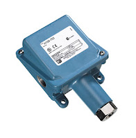 |
| Pressure switch (courtesy of United Electric Controls) |
In making the connection between the normal state of switch contacts and the normal state of a process, one should relate the switch state to the process condition which would serve as the stimulus to change the switch state. For a limit switch, which responds to physical contact by an object, normal means the target is not contacting the switch. For a proximity switch, normal means the target is far away. A normal pressure switch condition occurs when the pressure is low, or may even indicate a vacuum. Level switches are normal when the level is empty. Normal for a temperature switch means the temperature is low. Flow switches are normal when there is a low flow rate, or the fluid is stopped. Both an understanding of normal as defined by the manufacturer of the switch and normal in terms of industry specific processes is necessary to correctly interpret the status of an operation. Once the concept of normal used in everyday conversation is uncoupled from your process control thinking, things fall into place easily.
Industrial Control Valve Actuator Operating Principles
The valve actuator is the component that physically moves the restrictor to vary the fluid flow. Three actuator types are used in control valves and they include spring and diaphragm, solenoid, and motor. As the name suggests the spring in diaphragm actuator uses a spring and a diaphragm to move the valve stem and plug.
A 15 PSI pneumatic signal enters the housing at the top of the actuator. As pressure is exerted on the diaphragm a downward force is applied against the spring which moves the restrictor. The diaphragm moves until it creates an equal but opposing force against the spring at which time the motion stops as the plug meets the valve seat. With no air pressure the restrictor is pushed upward by the spring to act as a normally open control valve. To vary the position of the restrictor and flow through the valve, a current to pressure transducer can be used to provide a three to 15 PSI signal to the diaphragm. At 3 PSI the valve is maintained open, and 15 PSI the valve is maintained closed. Pressures between the three to 15 PSI range proportionally change the flow of the valve. For example a pressure of 9 PSI applied to the diaphragm moves the spring and valve stem to 50 percent operating range.
For on /off control of the valve, a solenoid is used to actuate the valve to a fully closed or fully open position. Applying current to the coil generates a magnetic field that moves the plunger downward against the return spring. With zero current applied to the coil the spring pulls the plunger upwards to the fully open position for a normally open state control valve.
Another method for variable valve positioning uses a motor and is referred to as proportional control mode. Using a gear motor attached to the valve stem a servo amplifier provides a DC control signal that moves the valve to the desired position. Feedback is achieved with the wiper arm attached to the valve stem that sends a signal back to the servo amplifier where the position is monitored the servo amplifier drives the motor until the control signal is equal to the feedback signal.
Watch the video below for an illustrated explanation. For more information on control valves, contact Ives Equipment at 877-768-1600 or visit http://www.ivesequipment.com.
SITRANS FC430 Coriolis Flowmeter Wins Control Engineering’s 2017 Engineers’ Choice Award
 |
| SITRANS FC430 Coriolis Flow Meter |
The Siemens SITRANS FC430 Coriolis flow meter, with National Type Evaluation Program custody transfer approval, for volume and mass liquid flow, is a Control Engineering 2017 Engineers’ Choice Awards Winner.
Siemens Coriolis flow meters are user-friendly to set up and use day-to-day. The meters stand up to the most demanding process industry conditions and continue to operate in the noisiest of environments – from hazardous chemicals to fiscal metering, custody transfer to compressed natural gas fuel dispensing. Its compact design makes installation easy even in the tightest spaces.
For more information on Siemens products, visit Ives Equipment here or call (877) 768-1600.
Labels:
coriolis flowmeter,
Delaware,
Maryland,
New Jersey,
New York,
Pennsylvania,
Siemens,
SITRANS FC430,
Virginia
An Extremely Thin, Multipoint, Temperature Measuring System
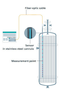 |
| Example of use (click for larger view) |
Recognizing temperature profiles and detailed understanding of the process are great challenges to plant operators. A fiber-optic based multipoint measuring system by SIEMENS enables you to determine a large number of temperature measuring points along a single sensor fiber and read out a temperature profile in a matter of seconds.
For example, you can quickly and precisely identify points overheating to help avoid or counteract potential damage to your product and/or equipment. Measured values are transmitted through an extremely thin sensor measuring lance. The diameter of the sensor measuring lance is independent of the number of measuring points. The response times of the sensors are also reduced because of the low thermal mass of the fiber optic.
Operation:
A continuously tunable laser generates light in the transmitter with a wavelength between 1500 and 1600 nm, which is output to the sensor measuring lances. The transmitter evaluates the reflected light component. Fiber Bragg Gratings (FBG) are inscribed at defined points on the sensor measuring lances, that reflect a defined wavelength. The wavelength reflected by the grating changes as a function of temperature and so indicates the temperature at the relevant measuring point. A gas cell with a fixed absorption line serves as a reference in the device, against which the determined wavelength is continuously calibrated.
 |
| Design of fiber measuring sensor (click for larger view) |
 |
| In use measuring catalytic conversion of gases in tube and tube-bundle reactors. |
- Tube and tube-bundle reactors
- Capillary and microreactors
- Distillation
- Rectifications
For more information in the SITRANS TO500 visit Ives Equipment or call (877) 768-1600.
Labels:
Delaware,
Maryland,
multipoint,
New Jersey,
New York,
Pennsylvania,
Siemens,
SITRANS TO500,
temperature sensor,
Virginia
Industrial, Fixed Point Gas Detection and Monitoring
 |
| Toxic / Flammable Gas Detection (courtesy of Sensidyne) |
Due to the variation in facilities and associated industrial purposes, the applicability and customization of fixed point monitors must be adaptable. The gases typically monitored by fixed point systems are industrial staples. Natural gas (methane) and hydrogen are inherently dangerous to work with due to both their combustible nature and flammability. Carbon monoxide, hydrogen sulfide, and chlorine are especially dangerous to those who work in and around facilities where they are used or produced, while otherwise harmless gases such as nitrogen can cause oxygen displacement leading to asphyxiation. Around-the-clock is the only way to monitor and mitigate the potential impact of such volatile substances; thanks to automation, the ability to be constantly vigilant of threats related to gases is possible.
 |
| Hazardous Gas Sensor (courtesy of Sensidyne) |
Sensing and evaluating these types of gases is a complex process, yet one which also showcases the powers of the associated technology. International certification standards like ATEX (derived from a French regulation acronym) and SIL (the safety integrity level) allow designers of gas detectors to match their products with the necessary parameters to ensure safe working environments. For example, one manufacturer's electrochemical gas sensor operates based on a principle involving two electrodes; the first electrode senses the toxic gas, and then the second electrode receives protons generated by the sensing electrode through an ion conductor. Output current which flows to an external circuit is proportional to the concentration of gas, therefore the current generated is measurable as an indicator of gas levels. Despite the fact that these sensors are primarily used in industry, there is also the potential for domestic applicability, automotive process control, and air quality control, among other uses. The different technological and practical applications of fixed point gas monitors allow for industry professionals to safely and capably navigate working environmental hazards for personnel and process protection.
For more information on industrial gas detection and monitoring, visit Ives Equipment at http://www.ivesequipment.com or call (877) 768-1600.
Valve Actuators: An Overview
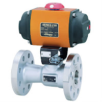 |
| Rack & Pinion Actuated Valve (courtesy of Flowserve Worcester) |
 |
| Electric Valve Actuator (courtesy of Flowserve Worcester) |
Thanks to actuators, multiple valves can be controlled in a process system in a coordinated fashion; imagine if, in a large industrial environment, engineers had to physically adjust every valve via a hand wheel or lever! While that manual arrangement may create jobs, it is, unfortunately, completely impractical from a logistical and economic perspective. Actuators enable automation to be applied to valve operation.
Pneumatic actuators utilize air pressure as the motive force which changes the position of a valve. Pressurized-liquid reliant devices are known as hydraulic actuators. Electric actuators, either motor driven or solenoid operated, rely on electric power to drive the valve trim into position. With controllers constantly monitoring a process, evaluating inputs, changes in valve position can be remotely controlled to provide the needed response to maintain the desired process condition.
 |
| Manual cryogenic ball valve (courtesy of Flowserve Worcester) |
traction throughout every industry. Valve actuators serve as the interface between the control intelligence and the physical movement of the valve. The timeliness and automation advantages of the valve actuators also serve as an immense help in risk mitigation, where, as long as the system is functioning correctly, critical calamities in either environmental conditions or to a facility can be pre-empted and quickly prevented. Generally speaking, manual actuators rely on hand operation of levers, gears, or wheels, but valves which are frequently changed (or which exist in remote areas) benefit from an automatic actuator with an external power source for a myriad of practical reasons, most pressingly being located in an area mostly impractical for manual operation or complicated by hazardous conditions.
Thanks to their versatility and stratified uses, actuators serve as industrial keystones to, arguably, one of the most important control elements of industries around the world. Just as industries are the backbones of societies, valves are key building blocks to industrial processes, with actuators as an invaluable device ensuring both safe and precise operation.
Contact Ives Equipment with any valve automation requirement you may have.
Basics of Variable Area Flowmeters (Rotameters)
 |
| Rotameter (variable area flowmeter courtesy of SIEMENS) |
Flow measurement is performed according to the float principle. The flowing medium lifts the conical float in the measuring ring. This increases the ring gap until an equilibrium is established between the buoyant force of the medium and the weight of the float. The height of the float is directly proportional to the flow rate. The movement of the float is transmitted from one magnet to another magnet in the display unit outside of the measuring tube.
The devices are particularly suitable for measuring:
- Water
- Liquids
- Anti-corrosives and lubricants
- Solvents
- Saturated and superheated steam • Food and beverages
- Industrial gases
The video below provides and excellent understanding of how rotameters operate.
Labels:
Delaware,
Flow,
Maryland,
New Jersey,
New York,
Pennsylvania,
Rotameter,
Siemens,
Variable Area,
Virginia
Basics of Turbine Flowmeters
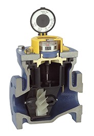 |
| Turbine flow meter internal view (courtesy of Niagara) |
In a single turbine flowmeter, there is a paramagnetic bladed turbine rotator which spins proportionally to the velocity of the subject fluid flowing through the pipe. Directly above the rotator and isolated from the fluid is a pickup coil, comprised of fine wire windings and a magnet. As the fluid flows and makes the suspended rotator spin, the rotator blades pass through the magnetic field of the pickup coil, generating a sinusoidal electrical signal. This signal is processed into a final calculation of total metered volume, as well as instantaneous flow rate and mass flow, based on the counts of turbine blade passage.
 |
| Turbine flow meter (courtesy of Niagara) |
Turbine flowmeters advantages additionally include low pressure drop and a compact design. Available sizes and materials of construction can accommodate a wide variety of applications in oil and gas, wastewater, utility, chemical, and food and beverage industries.
Proper instrument selection and configuration goes hand in hand with a proper installation toward successful project completion. Share your fluid measurement challenges with instrumentation specialists, combining your process knowledge with their product application expertise to develop effective solutions.
Labels:
Delaware,
flow control,
Maryland,
New Jersey,
New York,
Niagara,
Pennsylvania,
Turbine flow meters,
Virginia
Municipal Wastewater Treatment: A Lighter Look
While Disney-Pixar’s film Finding Nemo tells a fantastic story involving a father fish, his son, and the ocean, Nemo’s lucky that the plot of the film didn’t involve him being flushed down a toilet in a suburban home. If it had, Nemo would’ve undergone a crucial Odyssey before even reaching a river: he would’ve journeyed through a municipal wastewater treatment plant. While a jaunt through a municipal wastewater plant doesn’t sound as commercially attractive as adventuring through the ocean, the purity and quality of municipality waterways and their ecosystems depends on municipal wastewater plants’ implementation of standards through treatment, via an air-tight water purification process.
The goal of a municipal wastewater treatment plant is to act as a gateway between contaminated wastewater and the water sources where the wastewater eventually goes. For that reason, many wastewater treatment plants are built in low-lying areas, usually with easy to access to water sources, such as river. All the water which leaves the plant after processing, called the ‘effluent’, needs to meet a standardized level of quality. The Environmental Protection Agency (EPA) estimates that there are around 16,000 municipal treatment plants active in the U.S. today; all of them need to meet the same environmental requirements in terms of their treatment quality.
The primary treatment in the process utilized by municipal plants reduces solid objects and suspended solids in the water via a barrier – otherwise known as sedimentation. Nemo, unfortunately, probably wouldn’t’ve made it past here. The process aims to reduce the presence of solid objects, pathogenic (disease causing) bacteria, biodegradable organics (BOD’s), and excess nutrients found in the wastewater. Primary, or mechanical, treatment filters the solid objects, while secondary treatment focuses on biological elements of the water. According to the World Bank Group, 85% of BODs and associated solids are eliminated by the conclusion of secondary treatment, which correlates with the EPA’s standards and their emphasis on plants having thorough, precise, and controlled secondary treatment systems. Tertiary treatment systems are becoming more popular in plants, as the advancement of technology leads to an even more robust cleanliness demand. Especially at the tertiary level, valves are essential because computer-based instrumentation can open, close, and/or partially close valves to ensure that purification is correlating with process control.
The process controllers use level and pressure measurement instruments to evaluate the quantitative and qualitative aspects of the wastewater. The pressure and level sensors indicate that the treatment systems are functioning properly, but also that the water moves from station to station in the plant with the most efficiency and care. If the instrumentation being monitored by plant employees is incorrect, a glitch in the system could lead to a decrease in the quality of the effluent water, resulting in damage to the environment. The process technology and its controllers must be both automatically and manually sound, because reliable operators need a reliable system to produce a top-quality result.
Sorry, Nemo, the sequel isn’t taking place in a municipality anytime soon!
Labels:
Delaware,
Ives Equipment,
Maryland,
New Jersey,
New York,
Pennsylvania,
Virginia,
wastewater treatment
Subscribe to:
Posts (Atom)


