Showing posts with label wastewater treatment. Show all posts

Increasing Safety in Chemical Waste Water Treatment Plant

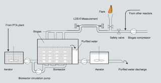
Waste water treatment and location of the measurement
Waste water treatment and location of the measurement.
Purified Terephthalic Acid (PTA) is the preferred raw material for the most common plastic products of daily life. The PTA production process generates various waste water streams which are high in organic content.

Purification of Process Waste Water

In the waste water treatment plant, the water treatment starts with aeration. The last step is an anaerobic bio reactor where the treatment is done in a controlled atmosphere. Micro organisms purify the water and produce biogas. Biogas roughly consists of 60 % methane and 40 % Carbon dioxide. This biogas is compressed and used as a fuel to reduce the net energy supply.

Although production or intrusion of oxygen into the reactors or pipes is highly unlikely, safety systems are installed. In case air enters unexpectedly into the process this first may result in a non-supporting atmosphere for the microbes and in the worst case the gas mixture may lead to an explosion.

Safety Guaranteed Using Siemens LDS 6

To ensure that oxygen never exceeds the maximum accepted concentration, the customer chose an in-situ measurement with the Siemens Laser Diode Spectrometer LDS 6. LDS 6 performs a continuous monitoring of the oxygen concentration in the biogas produced.
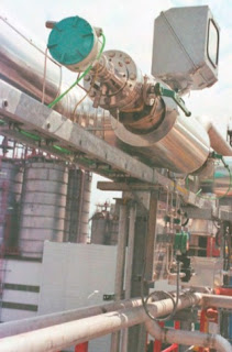
Measurement path and the two LDS 6 sensor heads
Measurement path and the
two LDS 6 sensor heads.

The response of the system is in three levels:
  1. In case the oxygen level exceeds 5 % an alarm is triggered.
  2. The threshold of 7 % causes an automatic nitrogen injection and the closure of a valve preventing the gas mixture from entering into the compressor.
  3. When the limit of 9 % is exceeded, this automatically shuts down the compressor.
The in-situ measurement leads to a fast and reliable measurement.

The stability and availability of the LDS 6 system is ensured by the integrated reference cell which provides a lifetime calibration. To be absolutely on the safe side, the customer operates a weekly safety check which involves opening a valve that allows a controlled air intake into the LDS 6 sensor heads. As the sensor heads are physically separated from the process by process windows, no oxygen may enter into the process. The reaction of the system shows in any of these tests once more the reliability of the measurement method used.

For more information about this application, or for any analytical instrument requirement, contact Ives Equipment by calling (877) 768-1600 or visiting https://www.ivesequipment.com.

Reprinted with permission from Siemens Case Study.

Municipal Wastewater Treatment: A Lighter Look

municipal wastewater treatment plant
While Disney-Pixar’s film Finding Nemo tells a fantastic story involving a father fish, his son, and the ocean, Nemo’s lucky that the plot of the film didn’t involve him being flushed down a toilet in a suburban home. If it had, Nemo would’ve undergone a crucial Odyssey before even reaching a river: he would’ve journeyed through a municipal wastewater treatment plant. While a jaunt through a municipal wastewater plant doesn’t sound as commercially attractive as adventuring through the ocean, the purity and quality of municipality waterways and their ecosystems depends on municipal wastewater plants’ implementation of standards through treatment, via an air-tight water purification process.

The goal of a municipal wastewater treatment plant is to act as a gateway between contaminated wastewater and the water sources where the wastewater eventually goes. For that reason, many wastewater treatment plants are built in low-lying areas, usually with easy to access to water sources, such as river. All the water which leaves the plant after processing, called the ‘effluent’, needs to meet a standardized level of quality. The Environmental Protection Agency (EPA) estimates that there are around 16,000 municipal treatment plants active in the U.S. today; all of them need to meet the same environmental requirements in terms of their treatment quality.

The primary treatment in the process utilized by municipal plants reduces solid objects and suspended solids in the water via a barrier – otherwise known as sedimentation. Nemo, unfortunately, probably wouldn’t’ve made it past here. The process aims to reduce the presence of solid objects, pathogenic (disease causing) bacteria, biodegradable organics (BOD’s), and excess nutrients found in the wastewater. Primary, or mechanical, treatment filters the solid objects, while secondary treatment focuses on biological elements of the water. According to the World Bank Group, 85% of BODs and associated solids are eliminated by the conclusion of secondary treatment, which correlates with the EPA’s standards and their emphasis on plants having thorough, precise, and controlled secondary treatment systems. Tertiary treatment systems are becoming more popular in plants, as the advancement of technology leads to an even more robust cleanliness demand. Especially at the tertiary level, valves are essential because computer-based instrumentation can open, close, and/or partially close valves to ensure that purification is correlating with process control.

The process controllers use level and pressure measurement instruments to evaluate the quantitative and qualitative aspects of the wastewater. The pressure and level sensors indicate that the treatment systems are functioning properly, but also that the water moves from station to station in the plant with the most efficiency and care. If the instrumentation being monitored by plant employees is incorrect, a glitch in the system could lead to a decrease in the quality of the effluent water, resulting in damage to the environment. The process technology and its controllers must be both automatically and manually sound, because reliable operators need a reliable system to produce a top-quality result.

Sorry, Nemo, the sequel isn’t taking place in a municipality anytime soon!

Industrial pH Control Basics

pH sensor
pH sensor courtesy of HF Scientific
Analytical measurement and control of pH within a system is necessary for many processes common applications include food processing, wastewater treatment, pulp & paper production, HVAC, power generation, and chemical industries.

pH display
pH display
courtesy of HF Scientific 
To maintain the desired pH level in a solution a sensor is used to measure the pH value. If the pH is not at the desired set point, a reagent is applied to the solution. When a high alkaline level is detected in the solution, an acid is added to decrease the pH level. When a low alkaline level is detected in the solution a base is added to increase the pH level. In both cases the corrective ingredients are called reagents.

Accurately applying the correct amount of reagent to an acid or base solution can be challenging due to the logarithmic characteristics a pH reaction in a solution. Implementing a closed-loop control system maintains the pH level within a certain range and minimizes the degree to which the solution becomes acidic or alkaline.

An example of an automatic pH level control system is a water treatment process where lime softened water is maintained at a pH of 9 using carbon dioxide as a reagent. As the untreated water (or influent) enters the tank, the pH is continuously monitored by the pH sensor. The sensor is the feedback device to the controller where the setpoint is compared to the control value. If the values are not equal, the controller sends a signal to the control valve that applies carbon dioxide to the tank. The reagent is applied to the tank at varying rates to precisely control the pH level. With the pH level at 11 detected by the sensor, the controller commands the control valve to open and introduce more carbon dioxide. As the increased carbon dioxide mixes with the influent, the pH is lowered in a controlled manner. Reaching the setpoint, the carbon dioxide flow is minimized and the process is continually monitored for variation. The effluent is the treated water that is discharged out of the tank. The process continues to provide the lime softened water at the desired pH level.

Wastewater Treatment Plants Save Big on Energy with Ultrasonic Controller

SIEMENS LUT400
SIEMENS LUT 400

For a water/wastewater treatment plant (W/WWTP), pumping is one of the most expensive parts of day-to-day operations. Varying from country to country, these costs range from 30 to 50 percent or more of a W/WWTP’s hydro bills – and in the future, this number will only increase as energy prices climb. Overall, water and wastewater treatment are one of the largest energy consumers in most municipalities, so any savings have an impact on more than just the W/WWTP.

By the Numbers

Just how much does pumping cost? Take your average 50 horsepower pump. In an hour, this pump consumes around 37 kilowatts. Do the math and at a cost of $0.065 per kilowatt hour (kWh) – Ontario, Canada’s off-peak price – that one pump costs a W/WWTP $12 every day, $4400 each year (as it has a running time of five hours per day).

But we know that many places, including Canada, the UK, Germany, South Africa, and Australia, have different rates according to the time of day or season energy is consumed. So while our single pump costs $0.065 per hour during low-energy periods, it now costs up to 80% more during Ontario’s peak-energy periods. So if the same company did all of its pumping during these peak periods, over the course of a year it would have spent an additional $3500! And remember this is just for a single pump – many W/WWTPs have hundreds of pumps, depending on a facility’s size.

Of course, no company is going to pump only in peak-energy periods – as we have just seen, that would be outrageously expensive. But, since wastewater treatment happens at all times of the day, facilities must pump during these high-cost periods.

So, How Do I Save Money?

SITRANS LUT400, Siemens’ newest ultrasonic controller, features two models that control
pump operating range
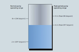
Figure 1: During peak periods, the pump operating range is
much smaller than in normal operation,
reducing the amount of time pumps must run.
economy-pumping regimes (also known as skimming): SITRANS LUT430 Level, Volume, Pump, and Flow Controller; and SITRANS LUT440 High Accuracy Open Channel Monitor, providing a full suite of advanced level, volume, and pump controls.

In normal operation, the controller will turn on pumps once water reaches the high level set point and then will begin pumping down to the low level set point. In economy pumping, the controller will pump wells down to their lowest level before the premium rate period starts, thereby maximizing the well’s storage capacity. The controller then maintains a higher level during the tariff period by using the storage capacity of the collection network. Pumping in this way ensures compliance with environmental regulations and minimizes energy use in peak tariff periods.

How Do I Set Up an Economy-pumping Regime?

Install SITRANS LUT400 ultrasonic controller and connect it to a Siemens Echomax transducer in
Siemens Echomax transducers
Siemens Echomax transducers installed in the well and the
SITRANS LUT400 controller measure the level of water and
control pump operations.
your well. You will set pump on and off points based on your local peak- energy periods. During summer in Ontario, for example, the peak tariff period is between 11 a.m. and 5 p.m.

In the winter, these times change to 7-11 a.m. and 5-7 p.m. You can program up to ve peak zones during one 24-hour period.

To begin setting up your economy-pumping regime, enable SITRANS LUT400’s Energy Savings function. Set the Peak Lead Time to 60 minutes to start pumping water down 60 minutes before the high-cost period begins so the well is at its lowest point. Depending on the volume of your well, you can set your Peak Lead Time to any amount between zero and 65,535 minutes.

On the controller, select the Peak Start Time of 11:00 a.m. and the Peak End Time of 5:00 p.m. Set your Peak ON Setpoint to nine meters and the Peak OFF Setpoint to six meters, as shown in Figure 1.

In Normal Operation mode, the controller starts the pump when water reaches eight meters and stops the pump at two meters. In Energy Saving mode, SITRANS LUT400 turns on the pump when water reaches nine meters and stops pumping at six meters, thus running the pump for the minimum amount of time during peak tariff periods. Cost-savings through economy-pumping regimes are simple to put in place with these steps.

Don’t forget that when you are setting up your controller, you can take advantage of SITRANS LUT400’s real-time clock for daylight saving time adjustment. The real-time clock is a useful feature – input your location’s daylight saving time and economy pumping will occur throughout the year without interruption.

Infiltration and Ingress (I&I) Monitoring
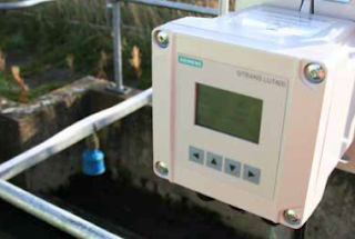
LUT400 controller and XRS-5 transducer
in a wet well application


Another cost-saving feature of this controller is in ltra- tion and ingress monitoring with SITRANS LUT400’s pumped volume feature and built-in datalogging capabilities.

In a closed collection network, it is inef cient and costly to pump rainwater entering the system due to leakages from degraded pipes. SITRANS LUT400 calculates pumped volumes, providing useful historical trending information for detecting abnormal increases of pumped water.

To use this feature, provide the known volume in the well between the pump’s ON and OFF setpoints. The controller will calculate the pumped volume based on the rate of level change in the well during pumping. It also calculates the in ow rate based on the rate of level change in the well just prior to pump startup.

SITRANS LUT400 logs this information for you to review via the controller’s communications options, or by connect- ing a USB cable and downloading logs directly to your computer. By comparing these results, you can see if in ow rates are greater due to rainwater entering the system. Repair those damaged pipes and the cost savings begin!

Through economy pumping and I&I monitoring, SITRANS LUT400 gives companies the potential for sig- ni cant energy savings. One SITRANS LUT400 user stated that every small change his company makes to reduce consumption has the potential to save millions of dollars each year.

For more information, contact:
Ives Equipment
(877) 768-1600