Showing posts with label Siemens. Show all posts

Simple Ways to Maximize the Efficiency of Your Process Control Application White Paper

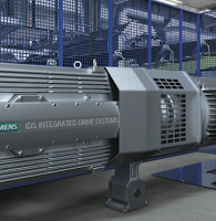
Siemens Integrated Drive Systems
A white paper courtesy of SIEMENS 

No matter what industry you’re in, the price of your inputs is bound to fluctuate – usually trending in a direction that doesn’t favor profits. You can’t control the rising costs of raw materials and energy, but you can control how much you get out of them. The simplest way to do this is by maximizing the efficiency of your equipment.

Performance and productivity are directly related to energy use, reliability and maintenance costs. The improved performance offered by a highly efficient drive train helps increase output and decrease energy consumption. It also reduces wear and tear, thereby limiting maintenance costs and downtime while extending the life of your equipment. To attain this level of efficiency, one need only turn to the application-specific engineering found in integrated drive systems. 

HydroRanger 200 Customer Loyalty Offer from Siemens

HydroRanger200
Take advantage of this
offer for the HydroRanger200
Time sensitive post!

Siemens Process Industries & Drives Division is pleased to bring you the enhanced HydroRanger 200 HMI ultrasonic level controller for measurement in a wide range of industrial applications including water/wastewater monitoring and pumping, inventory management, truck load-outs, and open channel monitoring.

Enhancements include faster commissioning with an improved HMI (Human Machine Interface) and graphical Quick Start Wizards as well as a redesigned enclosure with removable terminal blocks and wider communications.

The HydroRanger 200 HMI provides high performance measurement of level, flow, differential level, and volume conversion, with additional alarm and pump control functions. Siemens’ patented Sonic Intelligence signal processing technology differentiates between true and false echoes from obstructions or electrical noise, giving users repeatable, fast, and reliable measurements.

Siemens is making it easy for you to see the benefits this instrument has to offer. As a loyal customer, they are offering you a 15% discount toward the purchase of the enhanced HydroRanger(s) 200 HMI version.

Call Ives Equipment at 877-768-1600 to place your order.
Use discount code: SPR6029
(Offer valid until December 31, 2016).

Using Magmeters in Zero Upstream and Zero Downstream Applications

MagmeterThis video provides excellent information on installing magnetic flowmeters when you do not have optimal piping situations. The video also provides the viewer with an excellent overview of how Magmeters work.

The presentation reviews topics such as how Magmeter works, mounting configuration, best practices, alternatives for when required upstream/downstream piping distances are not available, the importance of a full pipe, and what kind of accuracy you can expect in less than ideal piping situations.

For more information on magnetic flowmeters visit this link or call Ives Equipment today at (877) 768-1600.

Wastewater Treatment Plants Save Big on Energy with Ultrasonic Controller

SIEMENS LUT400
SIEMENS LUT 400

For a water/wastewater treatment plant (W/WWTP), pumping is one of the most expensive parts of day-to-day operations. Varying from country to country, these costs range from 30 to 50 percent or more of a W/WWTP’s hydro bills – and in the future, this number will only increase as energy prices climb. Overall, water and wastewater treatment are one of the largest energy consumers in most municipalities, so any savings have an impact on more than just the W/WWTP.

By the Numbers

Just how much does pumping cost? Take your average 50 horsepower pump. In an hour, this pump consumes around 37 kilowatts. Do the math and at a cost of $0.065 per kilowatt hour (kWh) – Ontario, Canada’s off-peak price – that one pump costs a W/WWTP $12 every day, $4400 each year (as it has a running time of five hours per day).

But we know that many places, including Canada, the UK, Germany, South Africa, and Australia, have different rates according to the time of day or season energy is consumed. So while our single pump costs $0.065 per hour during low-energy periods, it now costs up to 80% more during Ontario’s peak-energy periods. So if the same company did all of its pumping during these peak periods, over the course of a year it would have spent an additional $3500! And remember this is just for a single pump – many W/WWTPs have hundreds of pumps, depending on a facility’s size.

Of course, no company is going to pump only in peak-energy periods – as we have just seen, that would be outrageously expensive. But, since wastewater treatment happens at all times of the day, facilities must pump during these high-cost periods.

So, How Do I Save Money?

SITRANS LUT400, Siemens’ newest ultrasonic controller, features two models that control
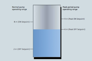
pump operating range
Figure 1: During peak periods, the pump operating range is
much smaller than in normal operation,
reducing the amount of time pumps must run.
economy-pumping regimes (also known as skimming): SITRANS LUT430 Level, Volume, Pump, and Flow Controller; and SITRANS LUT440 High Accuracy Open Channel Monitor, providing a full suite of advanced level, volume, and pump controls.

In normal operation, the controller will turn on pumps once water reaches the high level set point and then will begin pumping down to the low level set point. In economy pumping, the controller will pump wells down to their lowest level before the premium rate period starts, thereby maximizing the well’s storage capacity. The controller then maintains a higher level during the tariff period by using the storage capacity of the collection network. Pumping in this way ensures compliance with environmental regulations and minimizes energy use in peak tariff periods.

How Do I Set Up an Economy-pumping Regime?

Install SITRANS LUT400 ultrasonic controller and connect it to a Siemens Echomax transducer in
Siemens Echomax transducers
Siemens Echomax transducers installed in the well and the
SITRANS LUT400 controller measure the level of water and
control pump operations.
your well. You will set pump on and off points based on your local peak- energy periods. During summer in Ontario, for example, the peak tariff period is between 11 a.m. and 5 p.m.

In the winter, these times change to 7-11 a.m. and 5-7 p.m. You can program up to ve peak zones during one 24-hour period.

To begin setting up your economy-pumping regime, enable SITRANS LUT400’s Energy Savings function. Set the Peak Lead Time to 60 minutes to start pumping water down 60 minutes before the high-cost period begins so the well is at its lowest point. Depending on the volume of your well, you can set your Peak Lead Time to any amount between zero and 65,535 minutes.

On the controller, select the Peak Start Time of 11:00 a.m. and the Peak End Time of 5:00 p.m. Set your Peak ON Setpoint to nine meters and the Peak OFF Setpoint to six meters, as shown in Figure 1.

In Normal Operation mode, the controller starts the pump when water reaches eight meters and stops the pump at two meters. In Energy Saving mode, SITRANS LUT400 turns on the pump when water reaches nine meters and stops pumping at six meters, thus running the pump for the minimum amount of time during peak tariff periods. Cost-savings through economy-pumping regimes are simple to put in place with these steps.

Don’t forget that when you are setting up your controller, you can take advantage of SITRANS LUT400’s real-time clock for daylight saving time adjustment. The real-time clock is a useful feature – input your location’s daylight saving time and economy pumping will occur throughout the year without interruption.

Infiltration and Ingress (I&I) Monitoring
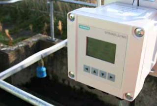
LUT400 controller and XRS-5 transducer
in a wet well application


Another cost-saving feature of this controller is in ltra- tion and ingress monitoring with SITRANS LUT400’s pumped volume feature and built-in datalogging capabilities.

In a closed collection network, it is inef cient and costly to pump rainwater entering the system due to leakages from degraded pipes. SITRANS LUT400 calculates pumped volumes, providing useful historical trending information for detecting abnormal increases of pumped water.

To use this feature, provide the known volume in the well between the pump’s ON and OFF setpoints. The controller will calculate the pumped volume based on the rate of level change in the well during pumping. It also calculates the in ow rate based on the rate of level change in the well just prior to pump startup.

SITRANS LUT400 logs this information for you to review via the controller’s communications options, or by connect- ing a USB cable and downloading logs directly to your computer. By comparing these results, you can see if in ow rates are greater due to rainwater entering the system. Repair those damaged pipes and the cost savings begin!

Through economy pumping and I&I monitoring, SITRANS LUT400 gives companies the potential for sig- ni cant energy savings. One SITRANS LUT400 user stated that every small change his company makes to reduce consumption has the potential to save millions of dollars each year.

For more information, contact:
Ives Equipment
(877) 768-1600

Food Processing: Belt Scales Improve Tomato Processor Efficiency and Productivity

Belt Scales Improve Tomato Processor Efficiency
Belt Scales Improve
Tomato Processing
The following post is a case history on using alternative technology to improve large scale food preparation process.  You'll read about how belt scales outperformed legacy equipment for a tomato peeling process and increasing yield.

Application:

A tomato processor located on the Paciļ¬c coast uses the latest technologies in peeling, dicing, and packaging tomatoes. They were preparing to replace some of their older weigh feeders because of declining performance. One of their main concerns with installing new weigh feeders was the cost of moving the existing conveying systems in order to accommodate new weigh feeders.

See the document below for the full case history:

Lost Plant Air a Hidden Source for Energy Savings

Save energy costs
Save energy costs by reducing
consumption of plant air.
Industrial plant air is one of the easiest sources of power to transmit and use. It’s also one of the most costly to generate. Information from the United States Department of Energy (DOE) indicates a wide variety of factors determine the cost of compressed air. These include, but are not limited to, local electrical energy cost, efficiencies of electric motors and compressors, load factors, and service time.

Plant maintenance are becoming more aware of air leaks and the subsequent increases in cost to overcome lost power because of those leaks. One of the major culprits for lost air in a plant is the pneumatic control valve positioner and the air required to operate them. In a typical process plant, there could be hundreds of control valves. Each control valve uses a positioner to move the valve actuator, based on a set point signal from a controller.

Control valve with SIPART
Control valve
with Siemens SIPART
It is the control valve positioner where the greatest air consumption savings lies.

Years ago, when electricity was cheap and when valve positioners were first introduced, plant maintenance and engineering were not concerned with something called the “bleed rate” of the positioner. Over the years though, plant personnel lost track of bleed rate and pretty much forgot that a positioner is just part of the system and it operates on air. Today, a modern process facility such as a power plant, refinery, or chemical plant can have several hundred control valves with positioners. The combined air loss due to the positioner “bleed rate” can be significant.

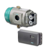
SIPART positioners
Siemens SIPART positioners
An immediate solution to this problem is to replace the control valve positioners with modern, energy-efficient, low-bleed models. One model, the Siemens SIPART PS2 has a proven track record of providing substantial savings to large plants. In one case, a tabacco company that had 2500 positioners was planning on spending $600,000 on a new compressor to increase output. After reviewing the capabilities of the low bleed positioner and running some tests, the plant decided to implement a plan for replacing the positioners which mitigated the need for a new compressor.

The significant change in technology came with the adoption of the adoption of a piezo ceramic valve block in low bleed positioners. Traditional positioners used an I/P and spool valve which both leaked air. Over time the leaks from these two parts is significant.

Could you and your plant be in the situation where lost energy efficiency through leaky positioners is costing big bucks? If you’re even the slightest bit concerned, call in an applications expert now for a system review.

Clamp-on Flowmeter Locates Hard-to-Find Water Plant Leak

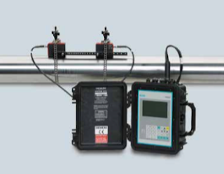
SITRANS FUP1010 clamp-on flowmeter
A rural water treatment plant in the Southwestern United States treats, stores, and distributes 325,00 gallons per day of water to the village it serves. The village consumes an average of 125,000 gallons a day and can store up to 1 million gallons.

The Problem

Unfortunately, the treatment plant was also losing 210,000 gallons a day due to an unknown leak.
Because of the leak, water storage was critically low at 100,000 gallons and the water service had to be temporarily shut off to half the village.

The village management hired a consultant company, at $1000.00 a day, to find the leak. The consultant worked for about a week without any luck.

The Solution

Read in the document below on how a Siemens SITRANS FUP1010 clamp-on flowmeter was used to find the leak.

Compact NTEP Approved Custody Transfer Coriolis Flowmeter Means Easier Installation and Space Savings

SITRANS FC430
SIEMENS SITRANS FC430
Running an industrial plant carries with it a very high level of responsibility. You must adhere to the highest standards of safety and hygiene, ensure that your final products are of consistent quality, and comply with stringent industry and governmental regulations.

By combining the Siemens SITRANS FCS400 sensor and SITRANS FCT030 transmitter, the digitally based SITRANS FC430 is suitable for applications within the process industries. It is also one of the first Coriolis systems worldwide to achieve SIL 2 and 3 approval in hardware and software, respectively – the ultimate assurance of safety and reliability.

The Siemens SITRANS FCS400 is the market’s most compact sensor, making installation and replacement easier than ever. It provides an accuracy rate of 0.1% and high sensitivity for optimal measurement of even low flows. The SITRANS FCS400 features a very stable zero point, low pressure loss, and high immunity to process noise and plant vibrations.

The SITRANS FCT030 transmitter delivers multi-parameter measurements with enhanced efficiency, simplicity and security. Available in a modular design, it can be remote or compact-mounted with all SITRANS FCS400 sensor sizes. An enclosed micro SD card serves as a removable database of operational information and provides direct access to all certificates and audit trails.

The SITRANS FC430 is ideal for a broad array of process industries and applications, including:
  • Chemical. Designed for optimal performance in hazardous areas and compliant with a wide variety of certificates and approvals, including SIL 2 (hardware), SIL 3 (software), FM, ATEX, CSA
  • Food & Beverage/Pharmaceutical. High level of accuracy improves quality control, while multi-parameter measurement ability strengthens process management. 
  • Oil & Gas. NTEP approved for custody transfer and capable of measuring mass flow directly, ensuring performance is not affected by fluctuating process conditions. Unique tube design results in minimal pressure loss and high resistance to process noise.
  • Affiliated Industries/OEMs. Highly customizable nature offers versatility to meet the needs of customers in many different businesses, from food and beverage to automotive to HVAC, to oil and gas to pulp & paper and beyond.
Formore information, contact:

Ives Equipment
877-768-1600

Compact Coriolis Flowmeter with NTEP Custody Transfer Approval

NTEP approval
NTEP approval for
custody transfer

When oil and gas are physically transferred from one operator to another, the term custody transfer is used to describe the transaction. It is understood as the transfer of fluid material defined by a metering device, at a given location, to another party. Custody transfer occurs at a variety of locations including from production platforms to ships, trucks, railcars, barges, and also at the final destination, such as the processing plant or refinery.

Accuracy is very important in custody transfer as both parties and instruments such as flowmeters must have approval by the organizations such as the American Petroleum Institute (API) or the National Conference on Weights and Measures (NCWM).

The National Type Evaluation Program (NTEP) is an evaluation program overseen by the National Conference on Weights and Measures (NCWM). Manufacturers who carry NTEP approval comply with local state and government regulations regarding transactions selling, purchasing, exchanging, custody transfer, or establishing the cost for services on based on weight.

NTEP approval
Compact Coriolis flowmeter
with NTEP approval
Siemens has announced the SITRANS FC430 Coriolis flow meter now has National Type Evaluation Program (NTEP) CT approval for the USA and Canada. The approval is for both the measurement of volume and mass liquid flow, and offers high accuracy measurement with minimum of pressure loss. The SITRANS FC430's performance and custody transfer approval makes it an excellent fiscal metering tool for diverse industries such as oil and gas, petrochemical, and food and beverage.

For more information, contact:
Ives Equipment
www.ivesequipment.com
877-768-1600

Coriolis Flow Sensor with 15 RA/230 Grit for Sanitary Applications

Sanitary Coriolis flow sensor
with 15 RA / 230 Grit finish
on wetted parts.
(Courtesy of Siemens)
In sanitary applications, the finish and the material must be designed for easy and reliable cleaning and sanitation. For decades agencies have required sanitary finishes to comply to minimum standards. But now, many food, Biotech, and Pharma companies are going beyond the minimum regulations and providing high-end finishes because of the reduced sanitation time and reduced bacteria growth these finishes facilitate.

Sanitary applications mandate that stainless steel equipment have a sanitary finish. In very general terms, “sanitary finish” means a smooth, scratch-free, non-corrosive finish. But it’s much more than that. To qualify the finish more accurately, there are two primary terms used:

Roughness Average, or RA: A standard for an average of the peaks and valleys of the metal’s surface, measured in microinches or micrometers. The lower the RA, the smoother the finish.

Grit: The size of the abrasive used in the metal polishing process. Higher grit numbers are associated with higher polishing.

For process control equipment manufacturers, achieving higher-end finishes is not an easy proposition. Providing better finishes requires experience and controlled processes for quality fabrication, as well as possible tooling and production floor changes. Working inside sanitary requirements requires careful handling to prevent contamination from the manufacturing environment. Not all process instrument manufacturers are capable of providing the required environment.

A Coriolis Flowmeter with 15 RA/230 Grit for Biotech and Pharma

Siemens is currently offering a 15 RA/230 Grit surface finish for the FCS400 Coriolis flow sensor internal wetted-tube parts as a special, and will soon be offering it as a standard.

A Coriolis sensor, with such a high end finish, is very attractive to many "clean" industries including chromatography, blood plasma fractioning, chemical synthesis phases, Active Pharmaceutical Ingredient (API) extraction/fermentation and purification, formulation, and  purified API.

Biotech and Pharma manufacturers, in particular, are poised to take advantage of the enhanced 15 RA/230 Grit finish coupled with the inherent benefits of the FCS400 Coriolis flow sensor, namely:
  1. Accurate measurement across the entire range
  2. Zero internal fabrication joints and self-draining design
  3. All metal surfaces eliminate risks from particulates from the breakdown of synthetic materials
  4. No internal fluids to leak into the process
  5. A direct mass flow rate/ and total
For more information, contact:

Ives Equipment
www.ivesequipment.com
(877) 768-1600

Siemens SITRANS LUT400 Pump Level Assist Routines

Siemens SITRANS LUT400

The Siemens SITRANS LUT400 series controllers are compact, single point, long-range ultrasonic controllers for continuous level, or volume measurement of liquids, slurries, and solids, and high accuracy monitoring of open channel flow.

The preconfigured pump routines in the SITRANS LUT 400 allow you to choose the best pump control scenario for your application. In the video below, you will see how the assist pump routines work.

The SITRANS LUT 400 has three assists pump routines available:
  • Alternate duty assist
  • Service ratio duty assist
  • Fixed duty assist
The fixed duty assist routine mainly uses one pump to control the liquid level. In this example, pump 1 will always start before pump 2. When the liquid level reaches the pump 1 “on” set point, pump one will turn on. If the liquid level continues to rise while pump one is running, then pump 2 will start. Pump 2 will assist pump 1 to lower the liquid level. Both pumps we'll turn off when the liquid level reaches the “off” set point. This pump sequence is fixed. Pump 1 will always start first, then if necessary, pump 2 will assist pump 1.

The alternate duty assist routine rotates between both pumps to control the liquid level. Pump 1 will start first. If it cannot keep up with the inflow, then pump 2 will turn on and assist pump 1. Both pumps will run until the liquid level reaches the pump “off” set point. On the next cycle, pump 2 will be the first pump to start. Pump 1 will assist pump 2 if it is necessary. The starting pump will continue to alternate between pump 1 and pump 2 after each filling cycle.

The service ratio duty assist routine rotates between both pumps based on the defined service ratio. In this example the service ratio is split equally between both pumps. The SITRANS LUT will choose which pump starts first based on this ratio. Since pump 1 has the lowest runtime hours it starts first. Pump 2 will assist pump 1 if the level continues to increase.  On the next cycle, pump 2 to will start first. Pump 1 will assist pump 2 if necessary. The service duty ratio assist routine will continue to maintain the runtime ratio for each filling cycle.


A Clean in Place (CIP) Mag Flow Meter with Pasteurized Milk Ordinance (PMO) Approvals

magmeter with PMO approval
Magmeter with PMO approval
(courtesy of SIEMENS)
Dairies have been hampered by a limited selection of flowmeters to process raw ingredients and maximize productivity. Faced with limited choices for instrumentation, the Food and Beverage Industry is always interested in new products and certification. In this case, the product is a "Clean in Place" (CIP) electromagnetic flow meter (Magmeter) with Pasteurized Milk Ordinance (PMO) approvals.

Clean-in-place (CIP) is a method of cleaning the interior surfaces of process equipmentpipes, vessels, and fittings, without disassembly. This is an invaluable technology in the dairy, brewery, beverage, processed foods, cosmetics, and pharmaceutical industries by providing a cleaning process which is faster, far less labor-intensive, more consistent, and with less chemical exposure to workers.

The Pasteurized Milk Ordinance, is published by the Food and Drug Administration further defines minimum standards and requirements for Grade A milk production and processing.

A Magmeter is an excellent flowmeter choice for dairy use because it is unaffected by suspended solids, viscosity, and temperature challenges typically found in food and beverage applications. Additionally, magnetic flowmeters provide:
  • Ease of installation with Tri-clamp fittings.
  • Stainless steel, obstruction less flow performance meets all sanitary requirements and is 3A certified.
  • Suitable for CIP and SIP cleaning.
  • IP67 I NEMA 4X rating that is upgradeable to IP68 /NEMA 6P.
Carrying a PMO approval provides the dairy with confidence and assurance that the magnetic flowmeters have been tested and approved precisely for use in their plant.

For more information, see the document below:

Remote Sensing of Gases Directly in the Process

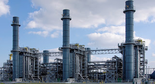
Electric power plant
Electric Power Plant
Industrial operations, whether for direct process control or emissions compliance monitoring, have a need for accurate, reliable measurement of specific gas concentrations within a flowing medium. Tunable diode laser spectroscopy, packaged for industrial use, provides a number of substantially positive attributes.

  • Rapid measurement.
  • Can be focused on a specific component of interest.
  • Multi-channel operation provides analysis of several components.
  • In situ installation can provide direct measurements within a stack, pipe, or duct without sample handling or conditioning.
  • Can measure NH3, HF, HCl, H2O, CO, CO2.
  • Internal reference cell provides long term stability.
  • Some models have continuous automatic calibration.
Siemens manufactures a line of tunable diode laser gas analyzers for industrial applications. In the company's own words, here is a basic description of how it works.

As a tunable diode laser-based technology this in-situ device enables high-performance measurements. The sensors (transmitter and receiver) are meant to be mounted directly on the process with no need of sampling systems. Laser light is sent from the transmitter, passing through the process gas, arriving at the detector on the receiver side. The measurements are carried out on-line with a very short response time permitting fast and effective cost-savings in process control. The laser characteristics allow single-line spectroscopy free of interferences. Since the band width of the laser light is extremely narrow, only the gas component of interest will interact with it. Other process influences, such as dust and temperature, are easily eliminated due to the excellent inherent compensation capabilities of this technique.


There is application assistance and more detailed information available from knowledgeable sales engineers in all localities. Combine your process mastery with their product application resources to meet the challenges posed by modern industrial process operation.


Basic Programming for the SITRANS F M Electromagnetic Flowmeter

The video below explains the basics of programming the SITRANS F M electromagnetic flowmeter.

The SITRANS F M MAG 5000 & 6000 are microprocessor-based transmitters engineered for high performance, easy installation, commissioning and maintenance. These transmitters are truly robust, cost-effective and suitable for all-round applications. The MAG 5000 has a measuring accuracy of ± 0.4% of the flow rate (incl. sensor), while the MAG 6000 has a measuring accuracy of ± 0.2% of the flow rate and can be fitted with optional plug-in communication modules.


Other Members of the SITRANS F M MAG Family:

SITRANS F M MAG 1100 is a wafer design sensor in stainless steel with highly resistant liners and electrodes and is designed for the general industry environment. The flangeless wafer design meets all flange standards. The SITRANS F M MAG 1100 is used in all industries where the corrosion-resistant stainless steel housing and the highly resistant liner and electrodes fit even the most extreme process media.

The SITRANS F M MAG 1100 F sensor is especially designed for the food & beverage and pharmaceutical industries and is available with hygienic and flexible process connections. It meets all sanitary requirements and is 3A certified and EHEDG approved.

The SITRANS F M  MAG 5100 W  with its patented liners of hard rubber NBR or ebonite and EPDM is a sensor for all water applications such as ground water, drinking water, cooling water, waste water, sewage or sludge applications.

SITRANS F M MAG 3100 is an electromagnetic flow sensor with a large variety of liners, electrode material and with grounding electrodes as standard, all this ensures a perfect fit for almost every flow application.
Also, measuring electrodes which are capable of withstanding the most extreme processes and various liners are available.

The SITRANS F M  MAG 3100 P sensor  is designed to meet the most common specifications within the chemical and process industries. It has PTFE or PFA liners and Hastelloy electrodes being the ideal combination. The fully welded construction provides a ruggedness that fits almost every flow application.

The SITRANS F M MAG 6000 I and the SITRANS F M MAG 6000 I Ex de transmitters have an measuring accuracy of + 0.2% of the flow rate and are designed to meet the demands of the process industry. Both versions are based on a microprocessor with a built-in alphanumeric display.

Township Water Authority Uses Ultrasonic Clamp-On Flowmeters to Avoid Surcharges for Exceeding Peak Limits

Ultrasonic Clamp-On Flowmeter
(courtesy of Siemens)
Reprinted with permission from Siemens Process Instrumentation

A suburban township buys their drinking water from a major municipal water district. The township’s water distribution system network has four connections to the larger municipality’s water transmission main. The municipality has many customers and has implemented contracts with each of its wholesale customers that limit the peak flows and the time of day in which they may occur. If the wholesale customer exceeds the limit, they are assessed significant surcharges.

Because of the potential surcharges, the wholesale customers can financially justify investing in solutions to better control their water demand, minimize the usage peaks, and control what time of day they occur. These measures include elevated water storage towers, as well as control valves at each of the connections to the municipal provider’s transmission main.

Challenge

The major municipal water district owns and operates “metering pits” with magmeters immediately upstream of the control vaults owned by each customer. However, as a rule, the signals from these meters are not made available to the any wholesale customers on a real time basis. Wholesale water customers are only given datalog summary reports from these meters on a routine schedule for billing purposes.

Without a method of measuring flows or getting flowrate data from the water district in advance, the township customer had no means of knowing, in real-time, the amount of flow they drew from the transmission main. Therefore, they did not know if or when they were exceeding the contractual peak flowrate limits and incurring significant surcharges from the water district until they were billed.

The township customer needs to know the flowrate at each of its four connections to the transmission main so they may control how much is being drawn at each site. They also need the total flow from the municipality’s transmission main, so they do not exceed their contractual peak demand.

The control vaults were initially installed without flowmeters. The intention was to use control valve position and upstream/ downstream (differential) pressure readings to estimate the flow through the control valve using the characteristic curve of the valve. This proved to be too complicated and cumbersome for their SCADA system to effectively implement.

Solution

The local Siemens representative worked with the township and their engineer to find a solution to measure the flow rate and totalize the volume of flow at each of the customer’s control vault sites. The most significant challenge was the piping configuration. All of the vaults were previously constructed without provisions for a flowmeter. The control valve vaults are very tight. The Siemens representative used a Siemens ultrasonic clamp-on flowmeter demo kit to demonstrate the technology to the customer, and prove that it would reliably meet their objectives. The vault with the worst piping configuration was selected for the demonstration. That would demonstrate that if the flowmeter would work in the worst site, it would work at the other three sites as well. However, if the Siemens flowmeter didn’t work in that site, the township would need to look at alternate, more costly, flow measurement technology for a solution. Within minutes of arriving on site, the unit was installed and providing reliable readings. The unit was allowed to log for a period of three days. After that, it was retrieved and compared to the readings from a competitive magmeter in the municipal water provider’s metering pit.

The logger on the Siemens clamp-on flowmeter provides helpful information on the quality of the velocity and flow measurements. This logged information helped establish and solidify the confidence of the owner and the engineer that the Siemens clamp-on meter would work for these applications.

Four key reasons the customer chose Siemens flowmeters:
  • The Siemens clamp-on flowmeter has the capability to make the tough measurements and provide information on the quality of those measurements. 
  • The attentive, professional and knowledgeable service they received from the local Siemens representative was well supported by Siemens personnel. 
  • The local representative provided the field service to install the transducers on the pipe, and commission the transmitters. 
  • The local representative conducted the demonstration and assisted the township engineer with their evaluation of the ultrasonic clamp-on flowmeter vs. magmeters owned by the water district. The major water district supported the Siemens ultrasonic clamp-on technology used by the township customer after they attended a Siemens Level & Flow Seminar held in their district. 
Benefits
  • Cost Savings - If they were not able to use the Siemens ultrasonic clamp-on flowmeters, the customer would have had to excavate and install a below-grade vault to house a magmeter and associated isolation and by-pass valves, along with conduit and wiring, at each of these four sites. This would have required cutting the water pipe and then going through a cumbersome disinfection process, both of which would have required lengthy permitting and costly testing. Further, some of the sites really had little or no room to accommodate such a structure or piping modifications. It is estimated these modifications would have totaled over $250,000. In comparison, the customer ended up spending $25,000 for the meters, and field service to install some conduit from the pipe to an existing above grade SCADA panel. 
  • Time Savings - The customer had already made improvements to the distribution system and installed four new control vaults. Their construction contracts were closing and they could not use their water tower until the new flow controls were added. Time was a critical factor. The customer saved 3-6 months in time by using the Siemens clamp-on flowmeters instead of having to construct new vaults to house magmeters. 
  • Improved Process Reliability - Now that the meters are in place, the customer can control how much water they are taking from the water district at each of these four locations, and ensure they do not exceed their contractual peak. They can now also properly manage the fill and draw of their elevated storage tank to offset peak demands, and fill/store during periods of low demand. 

The Coriolis Principle and It's Use in Flow Measurement

Image courtesy of
Wikipedia
The Coriolis effect acts on a medium that is accelerated through a rotating system, like a ball on a rotating disk its movement is straight, however, if the observer turns with the disk the ball is apparently deflected (see image).

The same effect occurs with a water hose that rotates around its own axis, like a skipping rope. As soon as water flows through the host also twists. The twisting is stronger or weaker, depending on the amount of water flowing through the hose.

Coriolis flow meters function according to the same principle (measuring the force resulting from acceleration caused by mass moving toward, or away from, a center of rotation).
Oscillation with flow
(courtesy of Wikipedia)
Oscillation without flow
(courtesy of Wikipedia)
 
The Coriolis effect also appears with an oscillating movement, and in a Coriolis flowmeter, two symmetric metal tubes are set vibrating by an internal driver coil. The tubes oscillate with a resonance frequency similarly to that of a tuning fork.

The oscillation is measured precisely by two pick-ups at the inlet and outlet sections. If liquids or gases flow through the tubes, a phase shift occurs the pickups measure the spatial and temporal displacement (twist). The amount of twist is proportional to the mass flow rate of fluid passing through the tubes. The greater the amount, the stronger the tubes oscillate outwards.

Finally, sensors and transmitters are used to measure the twist and create a linear flow signal as an output for monitoring and control.

This video, although marketing oriented, does a great job illustrating the Coriolis effect and how Coriolis flowmeters measure mass flow (the video references the Siemens SITRANS FC430 as the example).


Ultrasonic Level Measurement


Ultrasonic level instruments measure the distance from the transmitter (located at some high point) to the surface of a process material located farther below using reflected sound waves. The frequency of these waves extend beyond the range of human hearing, which is why they are called ultrasonic. The time-of-flight for a sound pulse indicates this distance, and is interpreted by the transmitter electronics as process level. These transmitters may output a signal corresponding either to the fullness of the vessel (fillage) or the amount of empty space remaining at the top of a vessel (ullage).

Ullage is the “natural” mode of measurement for this sort of level instrument, because the sound wave’s time-of-flight is a direct function of how much empty space exists between the liquid surface and the top of the vessel. Total tank height will always be the sum of fillage and ullage, though. If the ultrasonic level transmitter is programmed with the vessel’s total height, it may calculate fillage via simple subtraction:

Fillage = Total height − Ullage

If a sound wave encounters a sudden change in material density, some of that wave’s energy will be reflected in the form of another wave in the opposite direction. In other words, the sound wave will “echo” when it reaches a discontinuity in density20. This is the basis of all ultrasonic ranging devices. Thus, in order for an ultrasonic level transmitter to function reliably, the difference in densities at the interface between liquid and gas must be large. Distinct interfaces of liquid and gas almost always exhibit huge differences in density, and so are relatively easy to detect using ultrasonic waves. Liquids with a heavy layer of foam floating on top are more difficult, since the foam is less dense than the liquid, but considerably denser than the gas above.

A weak echo will be generated at the interface of foam and gas, and another generated at the interface of liquid and foam, with the foam acting to scatter and dissipate much of the second echo’s energy.

The instrument itself consists of an electronics module containing all the power, computation, and signal processing circuits; plus an ultrasonic transducer to send and receive the sound waves. This transducer is typically piezoelectric in nature, being the equivalent of a very high-frequency audio speaker.

The ISA-standard designations for each component would be “LT” (level transmitter) for the electronics module and “LE” (level element) for the transducer, respectively. Even though we call the device responsible for transmitting and receiving the sound waves a transducer (in the scientific sense of the word), its function as a process instrument is to be the primary sensing element for the level measurement system, and therefore it is more properly designated a “level element” (LE).

This photograph shows a typical installation for an ultrasonic level-sensing element (LE), here sensing the level of wastewater in an open channel:


If the ultrasonic transducer is rugged enough, and the process vessel sufficiently free of sludge and other sound-damping materials accumulating at the vessel bottom, the transducer may be mounted at the bottom of the vessel, bouncing sound waves off the liquid surface through the liquid itself rather than through the vapor space. As stated previously, any significant difference in material densities is sufficient to reflect a sound wave. This being the case, it shouldn’t matter which material the incident sound wave propagates through first:

This arrangement makes fillage the natural measurement, and ullage a derived measurement (calculated by subtraction from total vessel height).

Ullage = Total height − Fillage

As mentioned previously, the calibration of an ultrasonic level transmitter depends on the speed of sound through the medium between the transducer and the interface. For top-mounted transducers, this is the speed of sound through the air (or vapor) over the liquid, since this is the medium through which the incident and reflected wave travel time is measured. For bottom-mounted transducers, this is the speed of sound through the liquid. In either case, to ensure good accuracy, one must make sure the speed of sound through the “timed” travel path remains reasonably constant (or else compensate for changes in the speed of sound through that medium by use of temperature or pressure measurements and a compensating algorithm).

For more information, check out this online document or visit Ives Equipment at www.ivesequipment.com.


(Attribution to Tony R. Kuphaldt under Creative Commons Attribution 3.0 United States License)

Prevent Downtime: Make Sure Your Process Measurement Device Is Protected

You're a process measurement and control engineer. Everybody is looking to you to make things work smoothly. When things fail, chances are someone is going to point a finger at you and ask why you didn't think of that bizarre confluence of events that managed to take things down. Let's look at a piece of your universe where some careful consideration will help keep disaster at bay.
Industrial Flow Meters
Industrial Process Flow Meters
Courtesy Siemens Industry, Inc.

Industrial processes require measurement to produce predictable, consistent, and desirable outcomes. It follows that there will be numerous data gathering points throughout the physical extent of the process, each staffed by a transmitter designed to measure temperature, pressure, flow, or some other process variable used to assure conformance of the operating process with its specifications. Each process measurement device must be carefully selected for accuracy, stability, and a number of other technical elements that make it well suited to measure the dynamic activity of your industrial process. Proper technical selection of the measurement hardware is certainly a key function that leads to a successful project. What other factors may play a role in delivering a well functioning, long lasting process measurement system?

The technical aspects of a process measurement and control device are but one consideration in product specification and installation. They come into play only when the device is working. Look at the event or condition possibilities, even those with very low perceived probability, that might take the measurement device out of action. Your research and good judgement, along with input from experienced application engineers will help you decide which to incorporate into your design and specifications.

Industrial temperature transmitters
Industrial Temperature Transmitters
Courtesy Siemens Industry, Inc.
  • Know the very extremes of weather conditions that may occur at the physical location of the device.
    Weather data for almost anywhere in the world, and certainly every major industrialized country, is readily available. Your device should be able to withstand the onslaught of any documented local condition on record, with some headroom included. Even if the process is planned to be shut down in unusual weather conditions, the temperature transmitter or other device you specified needs to be able to survive and immediately return to service when the process is restarted. Find local weather data and make it part of your process measurement device specification and selection process.
  • Know the process generated extremes that can impact device functionality.
    Of course, you will select a pressure transmitter or other measurement device to accommodate the generally expected conditions associated with the process. Consider, though, what other conditions might be produced coincidental to the process. There may be machinery, valves, or other physical events not contemplated here that might, on occasion, produce a local condition that can damage your transmitter. Look for potential sources of vibration, shock, temperature, or other elements that might have potential to take your measurement device out of service.
  • Know the security exposure of the device.
    Something rarely considered in the past, an assessment of who might want to commit malicious acts against the process stakeholders or the process itself, and how they might do it, should now be a part of all project designs at some level. Additionally, the ability for anyone to impact process operation, directly or indirectly, through its measuring devices should be well understood.
  • Know the physical contact hazards.
    Measurement devices need to be accessible for calibration, maintenance, even real-time observation in some cases. They also need to be protected from impact resulting from human activity related to operation, maintenance, and repair of nearby items. Often, flow meters or other process variable transmitters are located adjacent to traffic areas of the facility. This eases access for maintenance and repair, but also exposes the devices to damage from other activity along those traffic lanes. Consider the physical location and protection of installed devices to thwart the effects of unplanned contact with dollies, carts, boxes, dropped tools, and a host of other unpredictable happenings.
  • Know moisture.
    The vast array of modern industrial measurement devices employ electronics in their function. These electronics, along with possibly other parts of the device, must be protected from the harmful effects of moisture. Specify the proper enclosure and connection devices, as well as the manner in which they need to be installed in order to assure proper protection. The entrance of moisture into a device enclosure can be very slow, almost undetectable in the short term. Assure that barriers to moisture entry are adequate, as well as, in appropriate cases, a way for accumulated moisture to easily exit the enclosure.
Invest your time and effort to produce a solid installation with a trouble free life cycle. Then sleep well. Consult with an experienced engineering sales team for help with your application.

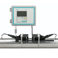
Installing the Siemens SITRANS FUS1010 Clamp-on Industrial Flowmeter

This video explains the installation of the Siemens SITRANS FUS1010 clamp-on flow meter, including identifying and selecting flow sensors, choosing a mounting location, and flowmeter programming. 

The SITRANS FUS1010 is one of the most versatile clamp-on ultrasonic flowmeters available. Because it can operate in either WideBeam transit time or Doppler mode, there is no need to change the meter when operating conditions change. This makes it suitable for virtually any liquid, even those with high aeration or suspended solids.