Wastewater Treatment Plants Save Big on Energy with Ultrasonic Controller

SIEMENS LUT400
SIEMENS LUT 400

For a water/wastewater treatment plant (W/WWTP), pumping is one of the most expensive parts of day-to-day operations. Varying from country to country, these costs range from 30 to 50 percent or more of a W/WWTP’s hydro bills – and in the future, this number will only increase as energy prices climb. Overall, water and wastewater treatment are one of the largest energy consumers in most municipalities, so any savings have an impact on more than just the W/WWTP.

By the Numbers

Just how much does pumping cost? Take your average 50 horsepower pump. In an hour, this pump consumes around 37 kilowatts. Do the math and at a cost of $0.065 per kilowatt hour (kWh) – Ontario, Canada’s off-peak price – that one pump costs a W/WWTP $12 every day, $4400 each year (as it has a running time of five hours per day).

But we know that many places, including Canada, the UK, Germany, South Africa, and Australia, have different rates according to the time of day or season energy is consumed. So while our single pump costs $0.065 per hour during low-energy periods, it now costs up to 80% more during Ontario’s peak-energy periods. So if the same company did all of its pumping during these peak periods, over the course of a year it would have spent an additional $3500! And remember this is just for a single pump – many W/WWTPs have hundreds of pumps, depending on a facility’s size.

Of course, no company is going to pump only in peak-energy periods – as we have just seen, that would be outrageously expensive. But, since wastewater treatment happens at all times of the day, facilities must pump during these high-cost periods.

So, How Do I Save Money?

SITRANS LUT400, Siemens’ newest ultrasonic controller, features two models that control
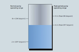
pump operating range
Figure 1: During peak periods, the pump operating range is
much smaller than in normal operation,
reducing the amount of time pumps must run.
economy-pumping regimes (also known as skimming): SITRANS LUT430 Level, Volume, Pump, and Flow Controller; and SITRANS LUT440 High Accuracy Open Channel Monitor, providing a full suite of advanced level, volume, and pump controls.

In normal operation, the controller will turn on pumps once water reaches the high level set point and then will begin pumping down to the low level set point. In economy pumping, the controller will pump wells down to their lowest level before the premium rate period starts, thereby maximizing the well’s storage capacity. The controller then maintains a higher level during the tariff period by using the storage capacity of the collection network. Pumping in this way ensures compliance with environmental regulations and minimizes energy use in peak tariff periods.

How Do I Set Up an Economy-pumping Regime?

Install SITRANS LUT400 ultrasonic controller and connect it to a Siemens Echomax transducer in
Siemens Echomax transducers
Siemens Echomax transducers installed in the well and the
SITRANS LUT400 controller measure the level of water and
control pump operations.
your well. You will set pump on and off points based on your local peak- energy periods. During summer in Ontario, for example, the peak tariff period is between 11 a.m. and 5 p.m.

In the winter, these times change to 7-11 a.m. and 5-7 p.m. You can program up to ve peak zones during one 24-hour period.

To begin setting up your economy-pumping regime, enable SITRANS LUT400’s Energy Savings function. Set the Peak Lead Time to 60 minutes to start pumping water down 60 minutes before the high-cost period begins so the well is at its lowest point. Depending on the volume of your well, you can set your Peak Lead Time to any amount between zero and 65,535 minutes.

On the controller, select the Peak Start Time of 11:00 a.m. and the Peak End Time of 5:00 p.m. Set your Peak ON Setpoint to nine meters and the Peak OFF Setpoint to six meters, as shown in Figure 1.

In Normal Operation mode, the controller starts the pump when water reaches eight meters and stops the pump at two meters. In Energy Saving mode, SITRANS LUT400 turns on the pump when water reaches nine meters and stops pumping at six meters, thus running the pump for the minimum amount of time during peak tariff periods. Cost-savings through economy-pumping regimes are simple to put in place with these steps.

Don’t forget that when you are setting up your controller, you can take advantage of SITRANS LUT400’s real-time clock for daylight saving time adjustment. The real-time clock is a useful feature – input your location’s daylight saving time and economy pumping will occur throughout the year without interruption.

Infiltration and Ingress (I&I) Monitoring
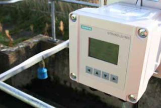
LUT400 controller and XRS-5 transducer
in a wet well application


Another cost-saving feature of this controller is in ltra- tion and ingress monitoring with SITRANS LUT400’s pumped volume feature and built-in datalogging capabilities.

In a closed collection network, it is inef cient and costly to pump rainwater entering the system due to leakages from degraded pipes. SITRANS LUT400 calculates pumped volumes, providing useful historical trending information for detecting abnormal increases of pumped water.

To use this feature, provide the known volume in the well between the pump’s ON and OFF setpoints. The controller will calculate the pumped volume based on the rate of level change in the well during pumping. It also calculates the in ow rate based on the rate of level change in the well just prior to pump startup.

SITRANS LUT400 logs this information for you to review via the controller’s communications options, or by connect- ing a USB cable and downloading logs directly to your computer. By comparing these results, you can see if in ow rates are greater due to rainwater entering the system. Repair those damaged pipes and the cost savings begin!

Through economy pumping and I&I monitoring, SITRANS LUT400 gives companies the potential for sig- ni cant energy savings. One SITRANS LUT400 user stated that every small change his company makes to reduce consumption has the potential to save millions of dollars each year.

For more information, contact:
Ives Equipment
(877) 768-1600

Monitoring and Control of Carbon Monoxide Emissions in a Parking Structure

Parking lot CO2 Monitor
(courtesy of CONSPEC)
Reprinted with permission by CONSPEC


Carbon monoxide (CO) emissions from motor vehicles can have detrimental effects on the air quality inside subterranean parking garages. CO, an odorless, tasteless and colorless gas, is the leading cause of accidental poisoning deaths in the United States. The Centers for Disease Control estimates that CO poisoning claims nearly 500 lives and accounts for more than 15,000 visits to emergency rooms annually. When not properly ventilated, CO concentrations can build to toxic levels. Also when CO emissions fill a space, the oxygen in that space is depleted, causing asphyxiation.

In an underground parking garage without adequate ventilation, CO can easily exceed NIOSH and OSHA recommendations, and put workers, tenants and commuters at severe health and safety risks. Several states have passed laws to protect parking garage personnel from CO exposure.

Ventilation systems, therefore, are a must for today’s mixed use underground parking facilities, but they can be costly to operate 24 hours, seven days a week. This is why mechanical contractors and HVAC specialists are increasingly specifying CO monitoring and ventilations systems for both new and existing parking structures.

CARBON MONOXIDE SENSING TECHNOLOGIES

Not all CO sensors are alike. Electrochemical sensing technology provides many advantages over the older semiconductor (“solid state”) sensors or infrared sensors. Electrochemical sensors offer high resolution (≤ 0.5 ppm), a linear signal, long-term stability (≥5% over the lifetime of the sensor) and immunity to false alarms caused by “nuisance gases.”

The best CO sensing technologies will also alert facility and emergency personnel, via cell phone, in the case of dangerous concentrations of CO. Use of CO monitoring and ventilation can not only protect human health, but also can help prevent fire, as increased CO levels can sometimes predict the imminent threat of fire.

While inadequate ventilation can drastically increase the risks of liability, continuous operation of ventilation systems can
be costly. To minimize heat loss in winter, as well as conserve energy used by the ventilation fan motors, some parking garage owners began to operate ventilation systems only during peak traffic times, that is, during the morning and evening rush hours. This, however, failed to take into account instances

in which a car was left idling or parking patterns varied from the norm. This explains the growing trend toward installation of CO monitoring and ventilation control systems.

AN ALTERNATIVE TO CONTINUOUS VENTILATION

To minimize health and safety liability issues, some garage owners decided to simply run ventilation systems continuously, but this created other problems. Jeff Aiken, a project manager with Professional Mechanical Contractors, Inc., notes that continuous fan operation can mean continuous annoyance for tenants in apartments or condominiums close to fans.

“CO emissions also create tremendous liability issues,” Aiken noted, “but continuous operation is not a good solution. Installing a gas detection solves this dilemma.”

In response to the energy crisis in California in the 1980s, Conspec Controls developed a combined CO monitoring and ventilation system using electrochemical sensing technology. For maximum cost efficiency in new construction, the design should include an integrated CO monitoring and ventilation system.

The Conspec P2621 is often specified due to its large area of coverage. For instance, in a typical garage with ten-foot ceilings, one unit will cover 10,000 square feet, while competing systems require two units in the same space.

Examining the User Interface of the SensAlert ASI Gas Detector

The Sensidyne SensAlert ASI provides enhanced protection and dependability for critical safety applications where personnel, processes, and facilities are at risk. The third party certified SIL-2 SensAlert ASI offers dependability and versatility while remaining the easiest to install, commission, operate, and maintain.

The video below demonstrates the setting menu and the operator interface.

The product is third-party certified to IEC61508 Level 2 (SIL-2) for both hardware and software with certification to global hazardous area and performance standards. The Test-on-Demand feature with on-board gas generator provides remote functionality checks with generated gas while Predictive Sensor End-of-Life Indication provides advanced warning of impending sensor failure.

SensAlert ASI is a universal instrument platform for toxic & combustible gas detection and oxygen monitoring. Intrinsically safe or explosion proof installation configurations with options for remote sensors and gassing, duct mount, and sample-draw maximize application versatility. Intrinsically safe or explosion proof installation configurations for remote sensors and gassing, duct mount, and sample-draw maximize application versatility. The sensor head accepts all Plus Series sensor technologies – infrared, catalytic bead, and electro-chemical. Assignable and configurable relays together with communication options provide broad flexibility. The SensAlert ASI I.S. sensor head can be remote mounted up to 100 feet (30m) from the transmitter providing a useful option to position the transmitter in a personnel-accessible location while positioning the sensor closer to potential hazards.

Food Processing: Belt Scales Improve Tomato Processor Efficiency and Productivity

Belt Scales Improve Tomato Processor Efficiency
Belt Scales Improve
Tomato Processing
The following post is a case history on using alternative technology to improve large scale food preparation process.  You'll read about how belt scales outperformed legacy equipment for a tomato peeling process and increasing yield.

Application:

A tomato processor located on the Paciļ¬c coast uses the latest technologies in peeling, dicing, and packaging tomatoes. They were preparing to replace some of their older weigh feeders because of declining performance. One of their main concerns with installing new weigh feeders was the cost of moving the existing conveying systems in order to accommodate new weigh feeders.

See the document below for the full case history:

2 Wire, 3 Wire, and 4 Wire RTD Sensor Connections

Industrial temperature transmitters
Industrial temperature
transmitters (courtesy of
Siemens)
Industrial temperature transmitters are devices that measure the temperature of a process and provide a measurable output over some desired temperature range. Industrial temperature transmitters primarily use either of two popular temperature sensors - the thermocouple or the RTD (resistance temperature detector). The RTD changes resistance as process temperature changes, while a thermocouple provides a changing micro-voltage with process temperature change. RTDs are inherently more accurate, but require excitation voltage. There are three style RTD's - 2-wire, 3-wire, and 4-wire.


Proper connections for all three types of RTD sensor to a user- configurable transmitter are shown in the following illustrations:

proper wiring of RTDs
Proper wiring of RTDs
It is critically important to note that the common connections shown by the symbols for 3- and 4-wire RTD sensors represent junction points at the sensor; not terminals jumpered by the technician at the time of installation, and not internal jumpers inside the transmitter. The whole purpose of having 3-wire and 4-wire RTD circuits is to eliminate errors due to voltage drop along the current-carrying wires, and this can only be realized if the “sensing” wire(s) extend out to the RTD itself and connect there. If the transmitter’s sensing terminal(s) are only jumpered to a current- carrying terminal, the transmitter will sense voltage dropped by the RTD plus voltage dropped by the current-carrying wire(s), leading to falsely high temperature indications.

Click here for more information on industrial RTDs and temperature transmitters.

For more information about any temperature measuring application, contact:
Ives Equipment
www.ivesequipment.com
(877) 768-1600

Some of above content taken from Lessons In Industrial Instrumentation by Tony R. Kuphaldt – under the terms and conditions of the Creative Commons Attribution 4.0 International Public License.