Educational information on process control, industrial instrumentation, valves, valve automation and control valves. For additional information visit IvesEquipment.com or call 877-768-1600
Examining the User Interface of the SensAlert ASI Gas Detector
The Sensidyne SensAlert ASI provides enhanced protection and dependability for critical safety applications where personnel, processes, and facilities are at risk. The third party certified SIL-2 SensAlert ASI offers dependability and versatility while remaining the easiest to install, commission, operate, and maintain.
The video below demonstrates the setting menu and the operator interface.
The product is third-party certified to IEC61508 Level 2 (SIL-2) for both hardware and software with certification to global hazardous area and performance standards. The Test-on-Demand feature with on-board gas generator provides remote functionality checks with generated gas while Predictive Sensor End-of-Life Indication provides advanced warning of impending sensor failure.
SensAlert ASI is a universal instrument platform for toxic & combustible gas detection and oxygen monitoring. Intrinsically safe or explosion proof installation configurations with options for remote sensors and gassing, duct mount, and sample-draw maximize application versatility. Intrinsically safe or explosion proof installation configurations for remote sensors and gassing, duct mount, and sample-draw maximize application versatility. The sensor head accepts all Plus Series sensor technologies – infrared, catalytic bead, and electro-chemical. Assignable and configurable relays together with communication options provide broad flexibility. The SensAlert ASI I.S. sensor head can be remote mounted up to 100 feet (30m) from the transmitter providing a useful option to position the transmitter in a personnel-accessible location while positioning the sensor closer to potential hazards.
Labels:
Delaware,
Eastern Pennsylvania,
gas detection,
Maryland,
New Jersey,
New York,
safety,
SensAlert,
Sensidyne,
SIL,
Virginia,
West Virginia
Food Processing: Belt Scales Improve Tomato Processor Efficiency and Productivity
 |
| Belt Scales Improve Tomato Processing |
Application:
A tomato processor located on the Pacific coast uses the latest technologies in peeling, dicing, and packaging tomatoes. They were preparing to replace some of their older weigh feeders because of declining performance. One of their main concerns with installing new weigh feeders was the cost of moving the existing conveying systems in order to accommodate new weigh feeders.
See the document below for the full case history:
Labels:
belt scale,
Delaware,
Eastern Pennsylvania,
Maryland,
New Jersey,
New York,
Siemens,
Virginia,
weigh feeder,
weighing,
West Virginia
2 Wire, 3 Wire, and 4 Wire RTD Sensor Connections
 |
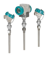
| Industrial temperature transmitters (courtesy of Siemens) |
Industrial temperature transmitters are devices that measure the temperature of a process and provide a measurable output over some desired temperature range. Industrial temperature transmitters primarily use either of two popular temperature sensors - the thermocouple or the RTD (resistance temperature detector). The RTD changes resistance as process temperature changes, while a thermocouple provides a changing micro-voltage with process temperature change. RTDs are inherently more accurate, but require excitation voltage. There are three style RTD's - 2-wire, 3-wire, and 4-wire.
 |
| Proper wiring of RTDs |
It is critically important to note that the common connections shown by the symbols for 3- and 4-wire RTD sensors represent junction points at the sensor; not terminals jumpered by the technician at the time of installation, and not internal jumpers inside the transmitter. The whole purpose of having 3-wire and 4-wire RTD circuits is to eliminate errors due to voltage drop along the current-carrying wires, and this can only be realized if the “sensing” wire(s) extend out to the RTD itself and connect there. If the transmitter’s sensing terminal(s) are only jumpered to a current- carrying terminal, the transmitter will sense voltage dropped by the RTD plus voltage dropped by the current-carrying wire(s), leading to falsely high temperature indications.
Click here for more information on industrial RTDs and temperature transmitters.
For more information about any temperature measuring application, contact:
Ives Equipment
www.ivesequipment.com
(877) 768-1600
For more information about any temperature measuring application, contact:
Ives Equipment
www.ivesequipment.com
(877) 768-1600
Some of above content taken from Lessons In Industrial Instrumentation by Tony R. Kuphaldt – under the terms and conditions of the Creative Commons Attribution 4.0 International Public License.
Combustion Analyzer Adds Higher Level of Safety by Measuring O2, Combustibles, and Methane
 The reliable identification of low combustion oxygen in a fired
heater or boiler has always been critical to the effectiveness of the
Burner Management System for proper control and safety.
The reliable identification of low combustion oxygen in a fired
heater or boiler has always been critical to the effectiveness of the
Burner Management System for proper control and safety.Low emission burners and aggressive firing control points to achieve increased efficiency and emission reductions have driven the industry to tighter control measures. But tighter control measures also hold a greater potential for combustion events. Reducing the risk of a combustion event has become a priority and has led to the implementation of Safety Instrumented Systems (SIS). This additional layer of safety is added to the Basic Process Control System.
The WDG-V has been designed to provide an additional layer of safety with the measurement of excess O2, Combustibles and Methane and by using these measurements to ensure the safe operation of the Burner Management System.
Solenoid Valve Operating Principle
 |
| Solenoid magnetic field |
At its most basic level a solenoid is an electromagnetic coil that uses magnetism produced by the flow of current to physically move the armature of a solenoid. The armature that is movable can be a rod or a metallic arm. One of the most common uses of solenoids are as the operators of valves.
A plunger solenoid contains a movable iron rod that is inserted into a coiled cylinder. The rod is connected to a plate with two contacts. With the aid of a spring the contacts are normally open. When an electrical current passes through the coil, it generates a magnetic field that attracts the rod into the coil chamber. The movement of rod will move the contacts into a closed position. When the current is turned off the magnetic force is removed and the tension in the spring forces the rod back out to its original resting position. This back-and-forth motion of the rod to control a circuit is used to operate a variety of mechanical devices such as valve seats and pneumatic poppets.
 |
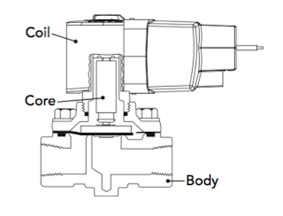
| Solenoid valve components |
- The solenoid (electromagnet) described above.
- A valve body containing one or more orifices.
 |
| ASCO Redhat Solenoid Valve |
This video provides a very basic visual understanding of the solenoid operating principle and how the mechanism works. From this video it is easy to understand how the linear movement created by the solenoid can be transformed into the movement necessary to open and close solenoid valves.
Lost Plant Air a Hidden Source for Energy Savings
 |
| Save energy costs by reducing consumption of plant air. |
Plant maintenance are becoming more aware of air leaks and the subsequent increases in cost to overcome lost power because of those leaks. One of the major culprits for lost air in a plant is the pneumatic control valve positioner and the air required to operate them. In a typical process plant, there could be hundreds of control valves. Each control valve uses a positioner to move the valve actuator, based on a set point signal from a controller.
 |
| Control valve with Siemens SIPART |
Years ago, when electricity was cheap and when valve positioners were first introduced, plant maintenance and engineering were not concerned with something called the “bleed rate” of the positioner. Over the years though, plant personnel lost track of bleed rate and pretty much forgot that a positioner is just part of the system and it operates on air. Today, a modern process facility such as a power plant, refinery, or chemical plant can have several hundred control valves with positioners. The combined air loss due to the positioner “bleed rate” can be significant.
 |
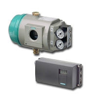
| Siemens SIPART positioners |
The significant change in technology came with the adoption of the adoption of a piezo ceramic valve block in low bleed positioners. Traditional positioners used an I/P and spool valve which both leaked air. Over time the leaks from these two parts is significant.
Could you and your plant be in the situation where lost energy efficiency through leaky positioners is costing big bucks? If you’re even the slightest bit concerned, call in an applications expert now for a system review.
Labels:
Delaware,
Eastern Pennsylvania,
energy,
Maryland,
New Jersey,
positioner,
Siemens,
SIPART,
valve,
Virginia,
West Virginia
Subscribe to:
Comments (Atom)
