Showing posts with label Process Control. Show all posts

Industrial Temperature Sensors: Basics of Thermocouples

industrial thermocouples
Industrial thermocouples
(courtesy of Applied Sensor Technology)
Thermocouples are the most widely used industrial temperature sensor found in industrial processes today. They are rugged, relatively inexpensive to manufacture, and provide fairly good accuracy.

Thermocouples operate on the "Seebeck Effect", which is the phenomena whereby two dissimilar metal conductors (wires), joined at two points, with one point kept at a known constant temperature, produce a measurable voltage difference between the two conductors.

Thermocouple types - such a type J, type K, type R, and type S - refer to the alloy combinations used for the conductors and are based on standardized color designations. 

Thermocouples are used widely in industrial processes in industries such as power generation, primary metals, pulp and paper, petro-chemical, and OEM equipment. They can be fabricated in protective wells, and can be housed in general purpose, water-tight, or explosion-proof housings.

The following video provides a basic visual understanding of thermocouple wire, how a T/C junction is determined, and also discusses thermocouple connectors, polarity and some aspects of construction (such as grounded vs. ungrounded vs. open tip).

High Performance, Low Cost, Industrial Safety Device

Series One Safety Transmitter
Safety Transmitter
Sadly, There are too many recent examples of catastrophic industrial accidents. New safety technologies exist today that can prevent or mitigate future disasters. The philosophy of safety is changing - the focus on plant safety has changed from reactive to a proactive approach. End users have a new sense of urgency toward safety processes.

The United Electric Controls (UE) Series One is a SIL-certified (SIL stands for safety integrity level) transmitter designed solely for safety, alarm, and shutdown applications, with reliability, speed, and fewer nuisance trips. It is also designed for both greenfield and brownfield installations, and is cyber secure.

A typical safety loop consists of sensors (such as a pressure transmitter), controllers, and final control elements. Most SIL-rated pressure transmitters require 300ms to communicate with the controller and up to 500ms for the controller to send a signal to the final control element (such as a valve). This may not be fast enough for critical applications. By connecting the One Series Safety Transmitter directly connected to the final control element, the signal speed is reduced to 100ms - a huge time savings when you're in the midst of a disaster. When used with blowers, pumps and compressors, the One Series makes up a complete safety system with a self-contained sensor, controller, and final control element (the switch) capable of SIL2 without additional safety instrumented function (SIF) components.

The below document provides detailed information about the Series One.


For more information, contact:

Ives Equipment
877-768-1600
www.IvesEquipment.com


Ultrasonic Level Measurement


Ultrasonic level instruments measure the distance from the transmitter (located at some high point) to the surface of a process material located farther below using reflected sound waves. The frequency of these waves extend beyond the range of human hearing, which is why they are called ultrasonic. The time-of-flight for a sound pulse indicates this distance, and is interpreted by the transmitter electronics as process level. These transmitters may output a signal corresponding either to the fullness of the vessel (fillage) or the amount of empty space remaining at the top of a vessel (ullage).

Ullage is the “natural” mode of measurement for this sort of level instrument, because the sound wave’s time-of-flight is a direct function of how much empty space exists between the liquid surface and the top of the vessel. Total tank height will always be the sum of fillage and ullage, though. If the ultrasonic level transmitter is programmed with the vessel’s total height, it may calculate fillage via simple subtraction:

Fillage = Total height − Ullage

If a sound wave encounters a sudden change in material density, some of that wave’s energy will be reflected in the form of another wave in the opposite direction. In other words, the sound wave will “echo” when it reaches a discontinuity in density20. This is the basis of all ultrasonic ranging devices. Thus, in order for an ultrasonic level transmitter to function reliably, the difference in densities at the interface between liquid and gas must be large. Distinct interfaces of liquid and gas almost always exhibit huge differences in density, and so are relatively easy to detect using ultrasonic waves. Liquids with a heavy layer of foam floating on top are more difficult, since the foam is less dense than the liquid, but considerably denser than the gas above.

A weak echo will be generated at the interface of foam and gas, and another generated at the interface of liquid and foam, with the foam acting to scatter and dissipate much of the second echo’s energy.

The instrument itself consists of an electronics module containing all the power, computation, and signal processing circuits; plus an ultrasonic transducer to send and receive the sound waves. This transducer is typically piezoelectric in nature, being the equivalent of a very high-frequency audio speaker.

The ISA-standard designations for each component would be “LT” (level transmitter) for the electronics module and “LE” (level element) for the transducer, respectively. Even though we call the device responsible for transmitting and receiving the sound waves a transducer (in the scientific sense of the word), its function as a process instrument is to be the primary sensing element for the level measurement system, and therefore it is more properly designated a “level element” (LE).

This photograph shows a typical installation for an ultrasonic level-sensing element (LE), here sensing the level of wastewater in an open channel:


If the ultrasonic transducer is rugged enough, and the process vessel sufficiently free of sludge and other sound-damping materials accumulating at the vessel bottom, the transducer may be mounted at the bottom of the vessel, bouncing sound waves off the liquid surface through the liquid itself rather than through the vapor space. As stated previously, any significant difference in material densities is sufficient to reflect a sound wave. This being the case, it shouldn’t matter which material the incident sound wave propagates through first:

This arrangement makes fillage the natural measurement, and ullage a derived measurement (calculated by subtraction from total vessel height).

Ullage = Total height − Fillage

As mentioned previously, the calibration of an ultrasonic level transmitter depends on the speed of sound through the medium between the transducer and the interface. For top-mounted transducers, this is the speed of sound through the air (or vapor) over the liquid, since this is the medium through which the incident and reflected wave travel time is measured. For bottom-mounted transducers, this is the speed of sound through the liquid. In either case, to ensure good accuracy, one must make sure the speed of sound through the “timed” travel path remains reasonably constant (or else compensate for changes in the speed of sound through that medium by use of temperature or pressure measurements and a compensating algorithm).

For more information, check out this online document or visit Ives Equipment at www.ivesequipment.com.


(Attribution to Tony R. Kuphaldt under Creative Commons Attribution 3.0 United States License)

Level Phase Split Detection and Measurement

Phase Level Detection
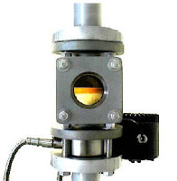
Phase level detection.
Need a system for continuous interface measurement? This system will monitor the emission phase and detect when phase A/B occurs, avoiding any flow of the emulsion into the incorrect area. When phases are separated, the system allows for tight control, which increases efficiency of separation of liquids A&B.

This system provides the ability to remotely view a process that may not normally be watched. Multiple viewing stations may be linked to the system output so various departments may monitor a process. Customers may purchase video monitors, amplifiers or screen splitters to enhance the system.

 
  • Ethernet systems allow the additional functionality of being able to remotely view through a Gigabit network system. Users can have access to live system images from their office networked computer. 
  • Software is available for customers that require additional functionality over simple viewing of a live image. Liquid level, color of different phases, and visual verification. 
System verifies the color of fluid in phase split and sends an output signal locating specific points of the interface. All measurements can be recorded and archived for a historical record. 


Monitor phase split in batch mode on organic droplets for increased product recovery. As the droplets appear the system warns of organic phase and the upcoming emulsion. The amount of early droplets and their retraction time will indicate the completeness of the separation. Once the split is identified and stopped, the operator has a visual verification from the video monitor. The color can then be analyzed to ensure there is no inversion.

For more information, contact:

Ives Equipment
601 Croton Road
King of Prussia, PA 19406
(877) 768-1600
www.ivesequipment.com

Upgrading a Mechanical Pressure Switch to an Electronic (Solid State) Version

This video demonstrates how to upgrade from a traditional mechanical pressure switch to a solid state pressure switch.

The example here uses the United Electric Controls One Series as the example.

This type of product (One Series) allows you to choose from explosion-proof, intrinsically safe and energy limited models that monitor gauge pressure, differential pressure or temperature. With up to two fully adjustable set points and deadbands, available 4-20 mA analog output, and absolutely no moving parts. They are used in a wide variety of applications where mechanical switches are not considered.


Prevent Downtime: Make Sure Your Process Measurement Device Is Protected

You're a process measurement and control engineer. Everybody is looking to you to make things work smoothly. When things fail, chances are someone is going to point a finger at you and ask why you didn't think of that bizarre confluence of events that managed to take things down. Let's look at a piece of your universe where some careful consideration will help keep disaster at bay.
Industrial Flow Meters
Industrial Process Flow Meters
Courtesy Siemens Industry, Inc.

Industrial processes require measurement to produce predictable, consistent, and desirable outcomes. It follows that there will be numerous data gathering points throughout the physical extent of the process, each staffed by a transmitter designed to measure temperature, pressure, flow, or some other process variable used to assure conformance of the operating process with its specifications. Each process measurement device must be carefully selected for accuracy, stability, and a number of other technical elements that make it well suited to measure the dynamic activity of your industrial process. Proper technical selection of the measurement hardware is certainly a key function that leads to a successful project. What other factors may play a role in delivering a well functioning, long lasting process measurement system?

The technical aspects of a process measurement and control device are but one consideration in product specification and installation. They come into play only when the device is working. Look at the event or condition possibilities, even those with very low perceived probability, that might take the measurement device out of action. Your research and good judgement, along with input from experienced application engineers will help you decide which to incorporate into your design and specifications.

Industrial temperature transmitters
Industrial Temperature Transmitters
Courtesy Siemens Industry, Inc.
  • Know the very extremes of weather conditions that may occur at the physical location of the device.
    Weather data for almost anywhere in the world, and certainly every major industrialized country, is readily available. Your device should be able to withstand the onslaught of any documented local condition on record, with some headroom included. Even if the process is planned to be shut down in unusual weather conditions, the temperature transmitter or other device you specified needs to be able to survive and immediately return to service when the process is restarted. Find local weather data and make it part of your process measurement device specification and selection process.
  • Know the process generated extremes that can impact device functionality.
    Of course, you will select a pressure transmitter or other measurement device to accommodate the generally expected conditions associated with the process. Consider, though, what other conditions might be produced coincidental to the process. There may be machinery, valves, or other physical events not contemplated here that might, on occasion, produce a local condition that can damage your transmitter. Look for potential sources of vibration, shock, temperature, or other elements that might have potential to take your measurement device out of service.
  • Know the security exposure of the device.
    Something rarely considered in the past, an assessment of who might want to commit malicious acts against the process stakeholders or the process itself, and how they might do it, should now be a part of all project designs at some level. Additionally, the ability for anyone to impact process operation, directly or indirectly, through its measuring devices should be well understood.
  • Know the physical contact hazards.
    Measurement devices need to be accessible for calibration, maintenance, even real-time observation in some cases. They also need to be protected from impact resulting from human activity related to operation, maintenance, and repair of nearby items. Often, flow meters or other process variable transmitters are located adjacent to traffic areas of the facility. This eases access for maintenance and repair, but also exposes the devices to damage from other activity along those traffic lanes. Consider the physical location and protection of installed devices to thwart the effects of unplanned contact with dollies, carts, boxes, dropped tools, and a host of other unpredictable happenings.
  • Know moisture.
    The vast array of modern industrial measurement devices employ electronics in their function. These electronics, along with possibly other parts of the device, must be protected from the harmful effects of moisture. Specify the proper enclosure and connection devices, as well as the manner in which they need to be installed in order to assure proper protection. The entrance of moisture into a device enclosure can be very slow, almost undetectable in the short term. Assure that barriers to moisture entry are adequate, as well as, in appropriate cases, a way for accumulated moisture to easily exit the enclosure.
Invest your time and effort to produce a solid installation with a trouble free life cycle. Then sleep well. Consult with an experienced engineering sales team for help with your application.

Installing the Siemens SITRANS FUS1010 Clamp-on Industrial Flowmeter

This video explains the installation of the Siemens SITRANS FUS1010 clamp-on flow meter, including identifying and selecting flow sensors, choosing a mounting location, and flowmeter programming. 

The SITRANS FUS1010 is one of the most versatile clamp-on ultrasonic flowmeters available. Because it can operate in either WideBeam transit time or Doppler mode, there is no need to change the meter when operating conditions change. This makes it suitable for virtually any liquid, even those with high aeration or suspended solids.


Going International With Your Design - Solenoid Operated Valves

Business is international
This is where your customers are now.
It's no secret to you, Engineer, that the world is densely populated with standards and approvals. No matter where you live or work, the process equipment designs that flow from your workstation, your team, your company, are more likely than ever to end up on foreign shores.


Solenoid Valve
Solenoid Valve
Solenoid operated valves are ubiquitous, even a little mundane in their apparent simplicity, but still require expertise for proper specification and application. The jurisdictional requirements for a valve assembly applied in the same manner can vary from one country to another. This can be especially important when designing equipment or processes that may be installed in different parts of the world, such as United States and European Union production plants of a single company.


Fortunately, many manufacturers now provide valves with multiple approvals from around the world to facilitate the use of a single component across a wide geographic and jurisdictional range. Even with this accommodation, it is still the specifying engineer’s responsibility to select the correct valve, not only for the application, but for a regulatory environment that is populated with standards and approvals that can be difficult to coordinate with confidence. One prominent valve manufacturer has authored a white paper that provides some insight into navigating this challenge, outlining an array of international approval agencies and providing a clear explanation of how T-codes (temperature codes) vary between US and EU agencies. The white paper is available on request and is a must-read for any engineer specifying or servicing solenoid valves.


Put A Process Control Sales Engineer On Your Team For Improved Outcome and Efficiency

Technical Sales Reps Provide Value
When it comes to specifying engineered products
a technical sales rep may be your best source.
Projects and tasks are best completed and accomplished through the proper application of the right resources. There exists an access point to high level technical knowledge and assistance that can be easily tapped and brought to bear on your successful task or project completion.  
Local distributors and representatives for process equipment and control manufacturers provide services that may help you save time and cost, while also achieving a better outcome for the entire project. Consider a few elements the technical sale rep brings to your project…

Product Knowledge: Sales engineers will be current on product offerings, proper application, and capabilities. They also have information regarding what products may be obsolete in the near future. This is an information source at a level not generally accessible to the public via the Internet.

Experience: As a project engineer, you may be treading on fresh ground regarding some aspects of your current assignment. There can be real benefit in connecting to a source with past exposure to your current issue. 

Access: Through a technical sales engineer, you may be able to establish a connection to “behind the scenes” manufacturer contacts with essential information not publicly available. The rep knows people, makes it his/her business to know the people that can provide answers to your  application questions.


Certainly, any solutions proposed are likely to be based upon the products sold by the representative. That is where considering and evaluating the benefits of any proposed solutions become part of achieving the best project outcome.

Develop a professional, mutually beneficial relationship with a technical sales team. Their success is tied to your success and they are eager to help you. 

Welcome to the Ives Equipment Blog

Thanks for visiting! In the upcoming weeks, months and years we hope to fill this site with interesting and useful information on a wide variety of process control topics. From pressure, temperature, level, flow, and analytical instrumentation, to control valves and valve automation, this blog will provide its visitors insight to how things work in industrial automation and process engineering.