Remote Telemetry Outstation / Data Logger for Water Utilities

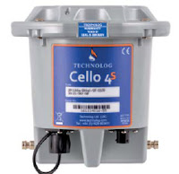
Technolog Cello 4S data logger
Technolog Cello 4S data logger.
The Technolog Cello 4S data logger monitors, records and transmits multiple site parameters over 2G (SMS/GPRS) or 3G networks, and provides a comprehensive multi-application solution for the Water Utilities and Industry.

The Cello 4S can have up to two pressure, eight user programmable digital or analogue inputs and two individually switched 12 Volt outputs for powering 4-20mA loops. Setup is made easy through an optional WiFi communication interface, and remote set-up, monitoring and control is facilitated through locally deployed PMAC software or web based WaterCore platform.
Technolog Cello 4S data logger
Technolog Cello 4S installed.

The Cello 4S provides closed loop control of pressure reducing valves, pressure sustaining valves and variable speed pumps, high accuracy battery monitoring for optimal asset management, is housed in a sturdy, portable, and waterproof to IP68 enclosure, offers 5 year battery life (typically) and includes water temperature measurement.


Or, view the specification sheet below:

Advanced Safety Integrity Universal Gas Transmitter

The Sensidyne SensAlert ASI provides enhanced protection and dependability for critical safety applications where personnel, processes, and facilities are at risk. The third-party certified SIL-2 SensAlert ASI offers dependability and versatility while remaining the easiest to install, commission, operate, and maintain.

SensAlert ASI is third-party certified to IEC61508 Level 2 (SIL-2) for both hardware and software with certification to global hazardous area and performance standards. The Test-on-Demand feature with on-board gas generator provides remote functionality checks with generated gas while Predictive Sensor End-of-Life Indication provides advanced warning of impending sensor failure.

For your convenience, we have posted the SensAlert ASI Users Manual below.

Vibrating Point Level Switch Operating Principles and Use

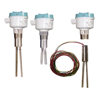
vibrating point level switch
Vibrating point level switches (SIEMENS)
When asked the primary reason to remember the year 1711, the event probably not on the minds of many is the invention of a device called the tuning fork. The tuning fork has been used as an source of resonating pitch for over three hundred years, and is still used to tune musical instruments today. While the tuning fork was initially applied to tune musical instruments, the concept of resonant frequency of a material or object has been utilized in numerous commercial, scientific, and industrial applications to provide feedback or insight into a process or operation. The vibrating fork level switch is one such industrial application where resonant frequency is used to deliver a data point or provide a control output for process operation.

The operating principle of the vibrating fork is based on the oscillating fork resonating at a known frequency in air when it is set in motion. Upon contacting a medium other than air, the resonant frequency is shifted, depending on the medium contacting or immersing the fork. Typically, fork-type level switches are installed on either the side or the top of a liquid process tank. An exciter keeps the fork oscillating, and a detector circuit monitors fork vibrating frequency, providing a change in the output signal when the frequency changes. Contact or immersion of the fork in liquid will change the fork vibrating frequency sufficiently to produce a change in output signal. Depending on the configuration of the level switch, it can function as a liquid level alarm, or provide a control output for a pump, valve, or other device. Sensor response, the change in fork vibration frequency, is a function of liquid density. Liquids with greater density will generally produce a larger frequency shift in the vibrating fork.

The wide use of vibrating level switches across various process industries is a testament to the reliability of the technology. The devices protect against overfill, indicate high and low points inside tanks, and are useful over a wide range of temperatures. A sturdy design, coupled with product variants that include a variety of sensor materials, selectable probe length, and specialized output features make vibrating fork switches applicable in many operations where level indication is needed. Chemical processing, mining, food and beverage, plastics, and other industries utilize the switches, thanks to their customizable designs and consistent performance. An advantage offered by vibrating fork level switches is a resistance to factors that sometimes confound other technologies employed for level indication. The devices will reliably function despite flow, bubbles, foam, vibration, and coating complexities related to the subject liquids. Additionally, vibrating fork switches are reliable in both high level and low level indication scenarios.

Highly viscous liquids are generally not good candidates for the application of a vibrating fork level switch. Some liquids present the potential for material accumulation between the forks, possibly resulting in poor performance. Both of these limitations are addressed by various design features incorporated by different manufacturers.

The SIEMENS SITRANS LVS200 is a vibrating point level switch for high or low levels of bulk solids. The standard LVS200 detects high, low or demand levels of dry bulk solids in bins, silos or hoppers. The liquid/solid interface version can also detect settled solids within liquids or solids within confined spaces such as feed pipes. It is designed to ignore liquids in order to detect the interface between a solid and a liquid. Additionally, the SITRANS LVS200 has an optional 4 to 20 mA output for monitoring buildup on the fork to determine when preventative maintenance should be performed in sticky applications.

For more information on any level sensing application, contact Ives Equipment by visiting http://www.ivesequipment.com of calling 877-768-1600.
The Ten Things Everyone Should Know about pH and ORP

Reprinted with permission from AquaMetrix Instruments

Here is a list of the ten things anyone in the business of measuring the pH or ORP of their process should know that will make his or her job more stress-free.

1. pH measurements are only good to 0.1 pH units.

Electrodes are funny things. They are the only electronic components that don’t even have specifications listed in their data sheets. One major figure of merit, the impedance of the glass electrode, is on the order of megaohms and can vary by a factor of two. Cross sensitivity to other ions (e.g. sodium), response time and differences between any two electrodes limit the accuracy of measurement. Expecting ac- curacy of greater than 0.1 pH units is

2. Speaking of accuracy... It is not the same as precision.

For a consistent process a pH probe can achieve precision of results to within 0.02 units but it’s accuracy will always be limited by variables such as calibration accuracy, high sodium content or careful routine calibration, however, will narrow the gap between the accuracy of readings closer to the lower level of precision.

3. ORP measurements are only good to ± 20 mV.

Once again the measurement of ORP might be characterized by a high precision but the accuracy of the reading is constrained by the dif culty of calibration, as explained in point 6, and the non-buffered calibration solutions that allow the ORP value of the calibration solutions to change over time. Whereas the buffered composition of pH calibration solutions insures that they will change minimally an ORP calibrations solution is a mixture of Fe2+ and Fe3+ salts. Just the addition of air to the mixture will increase the ORP of the mixture. So don’t look for “NIST traceable” on the label of an ORP calibration solution.

4. ORP measurements are relative.

The process electrode is nothing more than a platinum (or gold) band upon which oxidation (reduction) reactions take place. To complete the circuit, as in all potentiometric devices, is a
reference electrode. Usually that is the same Ag/AgCl electrode used in a pH probe so the REDOX potential that you read is the difference between the Pt band process electrode and the arbitrarily chosen reference electrode. What matters most with an ORP measurement is its change to an agreed upon standard.

5. pH calibration requires two points.

Calibration measures the response of an instrument as one changes the measurement variable in a known way. For pH measurements that measurement variable is the concentration of hydrogen ions. One calibrates a pH probe by drawing a line through points representing the response of a pH probe to more than one H+ ion concentrations (or pH values). Therefore calibration requires at least two points.

6. ORP calibration can only realistically be done with one point.

This sounds like a reversal of point 4 but it’s not. ORP is not a measure of any one species (e.g. H+ ions or oxygen molecules). It measures the collective REDOX potential of everything in the water. Furthermore calibration solutions, e.g. 200 mV Light’s solution and 600 mV Zobell’s solution are two completely different mixtures of reagents. Therefore all we can is choose one calibration solution and calibrate for it.

7. ORP measurements can be slow.

Stick an ORP probe in a calibration solution and you will get a steady reading with- in half a minute. Take the same probe and stick it in a glass of tap water and it might take 20 minutes for the reading to settle to the 200-300 mV that is typical of tap water. The response of the process electrodes to the REDOX reactions that take place on the surface of a Pt electrode depends on the speed of the many reactions that give the potential and the rate at which molecules diffuse through the water. The Fe2+ and Fe 3+ ions that comprise most of the ORP value in calibration solutions react very quickly with the Pt but the Cl- and dissolved oxygen that make up tap water react much more slowly. So the key to successful ORP measurement is patience.

8. pH measurements must be temperature compensated to be accurate.


A pH measurement is the determination of H+ ions in solution. Higher temperature causes the chemical activity to increase and the pH reading to increase accordingly. So we must remove the temperature effect by measuring it and using the well known Nernst equation to correct it for the reading at 250C. (The correction is quite simple. The pH value is proportional to temperature when the latter is an absolute value (i.e. in Kelvins).

9. ORP measurements are affected by temperature but are NOT corrected for it.

An ORP value simply reflects the ability of whatever is in the water to oxidize whatever contaminants are in the water. Of course oxidation speeds up at higher temperatures. But since ORP measures the rate of chemical reactions and not any one chemical species there is no need to correct it. However we can convert the temperature reading to the ORP that we would measure at 250 C so that we have a basis for comparing the chemistry of the process. That’s why we provide a temperature sensing thermistor or RTD with our differential ORP probes.

10. A differential probe properly cared for will last a long time but it won’t last forever.

Over time chemicals in the process make their way through the junction or salt bridge and into the pH 7 buffer that bathes the reference electrode. Manufacturers go to great length to minimize this contamination but they can only slow it down. Aquametrix differential probes allow the user to cheaply and quickly replenish both the pH 7 solution and the salt bridge so that our probes our industry leaders when it comes to probe lifetime. Nonetheless electrodes themselves lose their efficiency as the glass becomes contaminated and/or eroded by the process. However the good news that, with routine calibration and maintenance an Aquametrix differential probe can last for years in most environments. As the car ads say, “your mileage will vary” but rest assured there is no probe on the market that will outlast an Aquametrix differential probe... as long as you take good care of it.

Diaphragm Seals: Critical Isolation and Protection for Your Process Instruments

Diaphragm Seal
Diaphragm Seal courtesy of
AMETEK U.S. Gauge
Diaphragm seals play a critical role in protecting items like pressure switches, gauges, and transmitters from the fluid being evaluated by the sensor. The seal is a flexible membrane which both seals and isolates an enclosure. Pressure crosses the barrier without inhibition, but the material being contained does not. Typical materials composing diaphragm seals are elastomers, with rubbers being the prime substance in both general and specialty purposes.

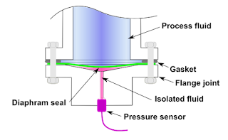
In the operating principle of the diaphragm seal, the chamber between the diaphragm and the instrument is filled with system fluid, allowing for the transfer of pressure from the process media to the sensor being protected. The seals are attached to the process by threaded, open flange, sanitary, or other forms of connection.  The seals can also be known as ‘chemical seals’ or ‘gauge guards’. Stainless steel, Carpenter 20, Hastelloy, Monel, Inconel, and titanium are used in high pressure environments, and some materials are known to work better when paired with certain chemicals.
Diagram of diaphragm seal
(courtesy of Wikipedia)

Sanitary processes, such as food and pharmaceuticals, use diaphragm seals to prevent against the accumulation of process fluid in pressure ports. If such a buildup were to occur, such as milk invading a pressure port on a pressure gauge and spoiling, the quality and purity of the fluid in the process may be compromised. Extremely pure process fluids, like ultra-pure water, could be contaminated by the metal surface of a process sensor. Pneumatic systems rely on the elimination of even the smallest pressure fluctuations, and diaphragm seals prevent those by ensuring the separation of the process materials from the sensors.

UE Pressure Switch
Diaphragm seals protect the sensors
on pressure switches like this
United Electric Controls model.
Despite their protective function and reliability, there are some potential complications related to diaphragm seals. Devices are now built to address and counter many potential issues related to process monitoring involving diaphragm seals. Products seek to eliminate any and all “dead space,” allow for continuous process flow, and are self-cleaning thanks to continuous flow design. Some high pressure seals come equipped with anti-clogging features, accomplished by the elimination of internal cavities while protecting gauges. Multi-purpose seals reduce temperature influence and improve instrument performance while pinpointing and diffusing areas of high stress. These pre-emptive measures result in longer instrument life-cycles and improve performance while ensuring protection from corrosion. The seals’ ability to protect both process quality and their own vitality make them essential components of process control.

For more information on diaphragm seals, visit Ives Equipment at http://www.ivesequipment.com or call (877) 768-1600.

Introduction to Flowmeters

magnetic flowmeters
Magnetic flowmeters
(courtesy of Siemens)
Flowmeters measure the rate or quantity of moving fluids, in most cases liquid or gas, in an open channel or closed conduit. There are two basic flow measuring systems: those which produce volumetric flow measurements and those delivering a weight or mass based measurement. These two systems, required in many industries such as power, chemical, and water, can be integrated into existing or new installations.

Turbine flow meter
Turbine flow meter
internal view
(courtesy of Niagara)
For successful integration, the flow measurement systems can be installed in one of several methods, depending upon the technology employed by the instrument. For inline installation, fittings that create upstream and downstream connections that allow for flowmeter installation as an integral part of the piping system. Another configuration, direct insertion, will have a probe or assembly that extends into the piping cross section. There are also non-contact instruments that clamp on the exterior surface of the piping add gather measurements through the pipe wall without any contact with the flowing media.

Because they are needed for a variety of uses and industries, there are multiple types of flowmeters classified generally into four main groups: mechanical, inferential, electrical, and other.
Variable Area Flowmeters
(courtesy of Siemens)

Quantity meters, more commonly known as positive displacement meters, mass flowmeters, and fixed restriction variable head type flowmeters all fall beneath the mechanical category. Fixed restriction variable head type flowmeters use different sensors and tubes, such as orifice plates, flow nozzles, and venturi and pitot tubes.

Inferential flowmeters include turbine and target flowmeters, as well as variable area flowmeters also known as rotameters.

Laser doppler anemometers, ultrasonic flowmeters, and electromagnetic flowmeters are all electrical-type flowmeters.

For any flowmeter application or question, visit Ives Equipment at www.ivesequipment.com or call (877) 768-1600.