Ives Equipment Business Groups

Ives Equipment organizes its extensive product line into four distinct groups:

Ives Equipment and Controls, providing instrumentation and control products to the chemical, petro-chemical, refining, bulk storage, primary metals, pulp & paper, powergen, gas & oil distribution and OEM markets.

Pharmaceutical, Bio-pharm, and Sanitary, providing hygienic, ultra-pure and sanitary instruments, connectors, fittings, tubing and gaskets to the pharma, bio-pharm, food and beverage, life-science and labortory industries.

Analytical Instruments, used to analyze process material samples and record the data for quality, conformance and compliance.

Water and Wastewater Treatment, providing instruments, analyzers, valves and controls for the transfer, storage, analysis, treatment, and logging of municipal and industrial water treatment systems.

Definition: Industrial Valve Actuator

pneumatic actuator
Pneumatic actuator on ball valve.
(Worcester)
Actuators are devices which supply the force and motion to open and close valves. They can be manually, pneumatically, hydraulically, or electrically operated. In common industrial usage, the term actuator generally refers to a device which employs a non-human power source and can respond to a controlling signal. Handles and wheels, technically manual actuators, are not usually referred to as actuators. They do not provide the automation component characteristic of powered units.

electric actuator
Electric actuator (Worcester)
The primary function of a valve actuator is to set and hold the valve position in response to a process control signal. Actuator operation is related to the valve on which it is installed, not the process regulated by the valve. Thus a general purpose actuator may be used across a broad range of applications.

In a control loop, the controller has an input signal parameter, registered from the process, and compares it to a desired setpoint parameter. The controller adjusts its output to eliminate the difference between the process setpoint and process measured condition. The output signal then drives some control element, in this case the actuator, so that the error between setpoint and actual conditions is reduced. The output signal from the controller serves as the input signal to the actuator, resulting in a repositioning of the valve trim to increase or decrease the fluid flow through the valve.

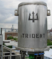
electro-hydraulic actuator
Electro-hydraulic actuator
(MIH Trident)
An actuator must provide sufficient force to open and close its companion valve. The size or power of the actuator must match the operating and torque requirements of the companion valve. After an evaluation is done for the specific application, it may be found that other things must be accommodated by the actuator, such as dynamic fluid properties of the process or the seating and unseating properties of the valve. It is important that each specific application be evaluated to develop a carefully matched valve and actuator for the process.

Hydraulic and electric actuators are readily available in multi-turn and quarter-turn configurations. Pneumatic actuators are generally one of two types applied to quarter-turn valves: scotch-yoke and rack and pinion. A third type of pneumatic actuator, the vane actuator, is also available.

For converting input power into torque, electric actuators use motors and gear boxes while pneumatic actuators use air cylinders. Depending on torque and force required by the valve, the motor horsepower, gearing, and size of pneumatic cylinder may change.

There are almost countless valve actuator variants available in the industrial marketplace. Many are tailored for very narrow application ranges, while others are more generally applied. Special designs can offer more complex operating characteristics. Ultimately, when applying actuators to any type of device, consultation with an application specialist is recommended to help establish and attain proper performance, safety and cost goals, as well as evaluation and matching of the proper actuator to the valve operation requirements. Share your fluid process control requirements with a specialist in valve automation, combining your own process knowledge and experience with their product application expertise to develop effective solutions.

Contact Ives Equipment for any valve actuator application. Visit http://www.ivesequipment.com or call (877) 768-1600.

Principles of Ultrasonic Flow in Industrial Clamp On Flow Meters

Ultrasonic Flow in Industrial Clamp On Flow Meters
The video below demonstrate the principles applied to industrial clamp on flow meters using the SITRANS FS as an example.

The ultrasonic technology of the SITRANS clamp on flow meter provides highly accurate measurement of liquids and gases. With no pressure drop or energy loss, a wide turn-down ratio and no need to cut the pipe or stop the flow, installation is easy and maintenance is minimal.

For more information about ultrasonic flow meters, contact Ives Equipment at 877-768-1600 or visit http://www.ivesequipment.com.

Happy Fourth of July from Ives Equipment

"We hold these truths to be self-evident, that all men are created equal, that they are endowed by their Creator with certain unalienable Rights, that among these are Life, Liberty and the pursuit of Happiness. — That to secure these rights, Governments are instituted among Men, deriving their just powers from the consent of the governed, — That whenever any Form of Government becomes destructive of these ends, it is the Right of the People to alter or to abolish it, and to institute new Government, laying its foundation on such principles and organizing its powers in such form, as to them shall seem most likely to effect their Safety and Happiness."

THOMAS JEFFERSON, Declaration of Independence

Refinery Gas Analyses Using Compact Gas Chromatographs and Gas Detectors

The analysis of trace permanent gases has many different fields of application in the petrochemical industry. One of the most important is for controlling the manufacturing process and the product quality. For example, some contaminants as carbon monoxide and carbon dioxide tend to deteriorate the catalysts in the propylene and ethylene polymer grade production.

An instrument for monitoring trace impurities is then required. Many different GC techniques are available on the market. Most of the techniques use a combination of TCD, FID and methanizer for the trace analysis of H2-O2-N2-CH4-CO-CO2 in propylene and ethylene. More precisely, an FID and a methanizer are used to trace CH4-CO and CO2. A TCD with Hydrogen or Helium carrier gas is used to trace O2-N2 detection. Finally, a second TCD with Argon or Nitrogen carrier gas must be added to trace H2 detection. These solutions require complex GC solutions with multiple detectors and multiple gas sources for carrier, fuel and air. On top of that, an FPD must be added in some cases when the trace analysis of H2S is required.

Read the application note below for more information. Contact Ives Equipment at (877) 768-1600 or visit http://www.ivesequipment.com for a consultation.

Understanding Hydrostatic Pressure

Understanding Hydrostatic Pressure
Pressure measurement is an inferential way to determine the height of a column of liquid in a vessel in process control. The vertical height of the fluid is directly proportional to the pressure at the bottom of the column, meaning the amount of pressure at the bottom of the column, due to gravity, relies on a constant to indicate a measurement. Regardless of whether the vessel is shaped like a funnel, a tube, a rectangle, or a concave polygon, the relationship between the height of the column and the accumulated fluid pressure is constant. Weight density depends on the liquid being measured, but the same method is used to determine the pressure.

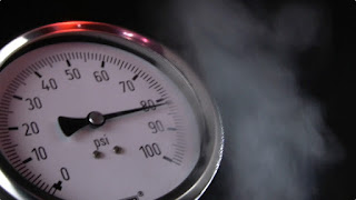
A common method for measuring hydrostatic pressure is a simple gauge. The gauge is installed at the bottom of a vessel containing a column of liquid and returns a measurement in force per unit area units, such as PSI. Gauges can also be calibrated to return measurement in units representing the height of liquid since the linear relationship between the liquid height and the pressure. The particular density of a liquid allows for a calculation of specific gravity, which expresses how dense the liquid is when compared to water. Calculating the level or depth of a column of milk in a food and beverage industry storage vessel requires the hydrostatic pressure and the density of the milk. With these values, along with some constants, the depth of the liquid can be calculated.

The liquid depth measurement can be combined with known dimensions of the holding vessel to calculate the volume of liquid in the container. One measurement is made and combined with a host of constants to determine liquid volume. The density of the liquid must be constant in order for this method to be effective. Density variation would render the hydrostatic pressure measurement unreliable, so the method is best applied to operations where the liquid density is known and constant.

Interestingly, changes in liquid density will have no effect on measurement of liquid mass as opposed to volume as long as the area of the vessel being used to store the liquid remains constant. If a liquid inside a vessel that’s partially full were to experience a temperature increase, resulting in an expansion of volume with correspondingly lower density, the transmitter will be able to still calculate the exact mass of the liquid since the increase in the physical amount of liquid is proportional to a decrease in the liquid’s density. The intersecting relationships between the process variables in hydrostatic pressure measurement demonstrate both the flexibility of process instrumentation and how consistently reliable measurements depend on a number of process related factors.

For more information on any type of pressure instrumentation, visit Ives Equipment at http://www.ivesequipment.com or call 877-768-1600.

An Explanation of Industrial Process Heating Technologies

Boiler providing steam for process heat
Boiler providing steam for process heat.
Process heating technologies can be grouped into four general categories based on the type of fuel consumed: fuel, steam, electric, and hybrid systems (which utilize a combination of energy types). These technologies are based upon conduction, convection, or radiative heat transfer mechanisms - or some combination of these. In practice, lower-temperature processes tend to use conduction or convection, whereas high-temperature processes rely primarily on radiative heat transfer. Systems using each of the four energy types can be characterized as follows:

Fuel-based process heating systems generate heat by combusting solid, liquid, or gaseous fuels, then transferring the heat directly or indirectly to the material. Hot combustion gases are either placed in direct contact with the material (i.e., direct heating via convection) or routed through radiant burner tubes or panels that rely on radiant heat transfer to keep the gases separate from the material (i.e., indirect heating).  Examples of fuel-based process heating equipment include furnaces, ovens, red heaters, kilns, melters, and high-temperature generators.

Steam-based process heating systems introduce steam to the process either directly (e.g., steam sparging) or indirectly through a heat transfer mechanism. Large quantities of latent heat from steam can be transferred efficiently at a constant temperature, useful for many process heating applications. Steam-based systems are predominantly used by industries that have a heat supply at or below about 400°F and access to low-cost fuel or byproducts for use in generating the steam. Cogeneration (simultaneous production of steam and electrical power) systems also commonly use steam-based heating systems. Examples of steam-based process heating technologies include boilers, steam spargers, steam-heated dryers, water or slurry heaters, and fluid heating systems.
Electricity-based process heating systems also transform materials through direct and indirect processes. For example, electric current is applied directly to suitable materials to achieve direct resistance heating; alternatively, high-frequency energy can be inductively coupled to suitable materials to achieve indirect heating. Electricity-based process heating systems are used for heating, drying, curing, melting, and forming. Examples of electricity-based process heating technologies include electric arc furnace technology, infrared radiation, induction heating, radio frequency drying, laser heating, and microwave processing.

Hybrid process heating systems utilize a combination of process heating technologies based on different energy sources and/or heating principles to optimize energy performance and increase overall thermal efficiency. For example, a hybrid boiler system may combine a fuel-based boiler with an electric boiler to take advantage of access to lower off-peak electricity prices. In an example of a hybrid drying system, electromagnetic energy (e.g., microwave or radio frequency) may be combined with convective hot air to accelerate drying processes; selectively targeting moisture with the penetrating electromagnetic energy can improve the speed, efficiency, and product quality as compared to a drying process based solely on convection, which can be rate-limited by the thermal conductivity of the material. Optimizing the heat transfer mechanisms in hybrid systems offers a significant opportunity to reduce energy consumption, increase speed/throughput, and improve product quality.

For more information, visit www.ivesequipment.com or call (877) 768-1600.