Industrial Control Valve Actuator Operating Principles

Control valve actuators control fluid in a pipe by varying the orifice size through which the fluid flows. Control valves contain two major components, the valve body and the valve actuator. The valve body provides the fluid connections and immovable restrictor comprised a valve stem and plug that is in contact with the fluid that varies the flow.

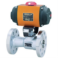
The valve actuator is the component that physically moves the restrictor to vary the fluid flow. Three actuator types are used in control valves and they include spring and diaphragm, solenoid, and motor. As the name suggests the spring in diaphragm actuator uses a spring and a diaphragm to move the valve stem and plug.

A 15 PSI pneumatic signal enters the housing at the top of the actuator. As pressure is exerted on the diaphragm a downward force is applied against the spring which moves the restrictor. The diaphragm moves until it creates an equal but opposing force against the spring at which time the motion stops as the plug meets the valve seat. With no air pressure the restrictor is pushed upward by the spring to act as a normally open control valve. To vary the position of the restrictor and flow through the valve, a current to pressure transducer can be used to provide a three to 15 PSI signal to the diaphragm.  At 3 PSI the valve is maintained open, and 15 PSI the valve is maintained closed. Pressures between the three to 15 PSI range proportionally change the flow of the valve. For example a pressure of 9 PSI applied to the diaphragm moves the spring and valve stem to 50 percent operating range.

For on /off control of the valve, a solenoid is used to actuate the valve to a fully closed or fully open position. Applying current to the coil generates a magnetic field that moves the plunger downward against the return spring. With zero current applied to the coil the spring pulls the plunger upwards to the fully open position for a normally open state control valve.

Another method for variable valve positioning uses a motor and is referred to as proportional control mode. Using a gear motor attached to the valve stem a servo amplifier provides a DC control signal that moves the valve to the desired position. Feedback is achieved with the wiper arm attached to the valve stem that sends a signal back to the servo amplifier where the position is monitored the servo amplifier drives the motor until the control signal is equal to the feedback signal.

Watch the video below for an illustrated explanation. For more information on control valves, contact Ives Equipment at 877-768-1600 or visit http://www.ivesequipment.com.

SITRANS FC430 Coriolis Flowmeter Wins Control Engineering’s 2017 Engineers’ Choice Award

SITRANS FC430 Coriolis flow meter
SITRANS FC430 Coriolis Flow Meter
The Siemens SITRANS FC430 Coriolis flow meter, with National Type Evaluation Program custody transfer approval, for volume and mass liquid flow,  is a Control Engineering 2017 Engineers’ Choice Awards Winner.

The Siemens SITRANS FC Coriolis flow sensor delivers mass flow, volume flow, density, fraction and temperature measurement of both liquids and gases with exceptionally high accuracy and low pressure drop.

Siemens Coriolis flow meters are user-friendly to set up and use day-to-day. The meters stand up to the most demanding process industry conditions and continue to operate in the noisiest of environments – from hazardous chemicals to fiscal metering, custody transfer to compressed natural gas fuel dispensing. Its compact design makes installation easy even in the tightest spaces.

For more information on Siemens products, visit Ives Equipment here or call (877) 768-1600.

An Extremely Thin, Multipoint, Temperature Measuring System

SITRANS TO500
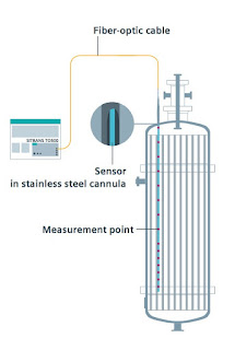
Example of use (click for larger view)
Do you want to install a very large number of measuring points in the smallest possible space with a low thermal mass?

Recognizing temperature profiles and detailed understanding of the process are great challenges to plant operators. A fiber-optic based multipoint measuring system by SIEMENS enables you to determine a large number of temperature measuring points along a single sensor fiber and read out a temperature profile in a matter of seconds.

For example, you can quickly and precisely identify points overheating to help avoid or counteract potential damage to your product and/or equipment. Measured values are transmitted through an extremely thin sensor measuring lance. The diameter of the sensor measuring lance is independent of the number of measuring points. The response times of the sensors are also reduced because of the low thermal mass of the fiber optic.

Operation:

A continuously tunable laser generates light in the transmitter with a wavelength between 1500 and 1600 nm, which is output to the sensor measuring lances. The transmitter evaluates the reflected light component. Fiber Bragg Gratings (FBG) are inscribed at defined points on the sensor measuring lances, that reflect a defined wavelength. The wavelength reflected by the grating changes as a function of temperature and so indicates the temperature at the relevant measuring point. A gas cell with a fixed absorption line serves as a reference in the device, against which the determined wavelength is continuously calibrated.
SITRANS TO500
Design of fiber measuring sensor (click for larger view)


SITRANS TO500
In use measuring catalytic conversion
of gases in tube and tube-bundle reactors.
Typical applications:
  • Tube and tube-bundle reactors
  • Capillary and microreactors
  • Distillation
  • Rectifications
For more information in the SITRANS TO500 visit Ives Equipment or call (877) 768-1600.

Industrial, Fixed Point Gas Detection and Monitoring

Gas detection
Toxic / Flammable
Gas Detection
(courtesy of Sensidyne)
In industry, the assessment and control of risk factors is a crucial element of process control. Commanding risk allows not only for peace of mind regarding environments involving hazardous materials, but also ensures - and prioritizes - the safety of those who work with said materials. Fixed point gas monitoring tracks and repeatedly evaluates the levels of potentially toxic or flammable gases in an industrial environment, typically using electrochemical, infrared, or catalytic bead sensors. A central monitoring station allows for an entire facility to operate under consistent watch, as the array of gas monitors throughout a facility form a system. Typical environments which utilize fixed point gas monitoring include CNG filling stations, fleet maintenance buildings, wastewater lift stations and treatment plants, pipelines, and refineries, among others.

Due to the variation in facilities and associated industrial purposes, the applicability and customization of fixed point monitors must be adaptable. The gases typically monitored by fixed point systems are industrial staples. Natural gas (methane) and hydrogen are inherently dangerous to work with due to both their combustible nature and flammability. Carbon monoxide, hydrogen sulfide, and chlorine are especially dangerous to those who work in and around facilities where they are used or produced, while otherwise harmless gases such as nitrogen can cause oxygen displacement leading to asphyxiation. Around-the-clock is the only way to monitor and mitigate the potential impact of such volatile substances; thanks to automation, the ability to be constantly vigilant of threats related to gases is possible.
Gas detection
Hazardous Gas Sensor
(courtesy of Sensidyne)

Sensing and evaluating these types of gases is a complex process, yet one which also showcases the powers of the associated technology. International certification standards like ATEX (derived from a French regulation acronym) and SIL (the safety integrity level) allow designers of gas detectors to match their products with the necessary parameters to ensure safe working environments. For example, one manufacturer's electrochemical gas sensor operates based on a principle involving two electrodes; the first electrode senses the toxic gas, and then the second electrode receives protons generated by the sensing electrode through an ion conductor. Output current which flows to an external circuit is proportional to the concentration of gas, therefore the current generated is measurable as an indicator of gas levels. Despite the fact that these sensors are primarily used in industry, there is also the potential for domestic applicability, automotive process control, and air quality control, among other uses. The different technological and practical applications of fixed point gas monitors allow for industry professionals to safely and capably navigate working environmental hazards for personnel and process protection.

For more information on industrial gas detection and monitoring, visit Ives Equipment at http://www.ivesequipment.com or call (877) 768-1600.

Valve Actuators: An Overview

Rack & Pinion Actuated Valve
(courtesy of Flowserve Worcester)
Valves are essential to industries which constitute the backbone of the modern world. The prevalence of valves in engineering, mechanics, and science demands that each individual valve performs to a certain standard. Just as the valve itself is a key component of a larger system, the valve actuator is as important to the valve as the valve is to the industry in which it functions. Actuators are powered mechanisms that position valves between open and closed states; the actuators are controllable either by manual control or as part of an automated control loop, where the actuator responds to a remote control signal. Depending on the valve and actuator combination, valves of different types can be closed, fully open, or somewhere in-between. Current actuation technology allows for remote indication of valve position, as well as other diagnostic and operational information. Regardless of its source of power, be it electric, hydraulic, pneumatic, or another, all actuators produce either linear or rotary motion under the command of a control source.
Electric Valve Actuator
(courtesy of Flowserve Worcester)

Thanks to actuators, multiple valves can be controlled in a process system in a coordinated fashion; imagine if, in a large industrial environment, engineers had to physically adjust every valve via a hand wheel or lever! While that manual arrangement may create jobs, it is, unfortunately, completely impractical from a logistical and economic perspective. Actuators enable automation to be applied to valve operation.

Pneumatic actuators utilize air pressure as the motive force which changes the position of a valve. Pressurized-liquid reliant devices are known as hydraulic actuators. Electric actuators, either motor driven or solenoid operated, rely on electric power to drive the valve trim into position. With controllers constantly monitoring a process, evaluating inputs, changes in valve position can be remotely controlled to provide the needed response to maintain the desired process condition.

Manual valve
Manual  cryogenic ball valve
(courtesy of Flowserve Worcester)
Manual operation and regulation of valves is becoming less prevalent as automation continues to gain
traction throughout every industry. Valve actuators serve as the interface between the control intelligence and the physical movement of the valve. The timeliness and automation advantages of the valve actuators also serve as an immense help in risk mitigation, where, as long as the system is functioning correctly, critical calamities in either environmental conditions or to a facility can be pre-empted and quickly prevented. Generally speaking, manual actuators rely on hand operation of levers, gears, or wheels, but valves which are frequently changed (or which exist in remote areas) benefit from an automatic actuator with an external power source for a myriad of practical reasons, most pressingly being located in an area mostly impractical for manual operation or complicated by hazardous conditions.

Thanks to their versatility and stratified uses, actuators serve as industrial keystones to, arguably, one of the most important control elements of industries around the world. Just as industries are the backbones of societies, valves are key building blocks to industrial processes, with actuators as an invaluable device ensuring both safe and precise operation.

Contact Ives Equipment with any valve automation requirement you may have.

Basics of Variable Area Flowmeters (Rotameters)

variable area flowmeter
Rotameter
(variable area flowmeter
courtesy of SIEMENS)
Rotameters (variable area flowmeters) can be used to measure many different types of liquids and gases passing through closed piping. The robust design means that it can also be used in harsh conditions. The various types of flange connections, linings and float materials satisfy the requirements of the pharmaceutical and chemical industries.

Flow measurement is performed according to the float principle. The flowing medium lifts the conical float in the measuring ring. This increases the ring gap until an equilibrium is established between the buoyant force of the medium and the weight of the float. The height of the float is directly proportional to the flow rate. The movement of the float is transmitted from one magnet to another magnet in the display unit outside of the measuring tube.

The devices are particularly suitable for measuring:
  • Water
  • Liquids
  • Anti-corrosives and lubricants
  • Solvents
  • Saturated and superheated steam • Food and beverages
  • Industrial gases
The video below provides and excellent understanding of how rotameters operate.

Basics of Turbine Flowmeters

Turbine flow meter
Turbine flow meter
internal view
(courtesy of Niagara)
Turbine flowmeters are displacement devices which mechanically measure fluid flow, specifically clean liquids and gases. Turbine flowmeters, so named for the axially mounted turbine these measuring instruments employ, measure the velocity of fluids flowing through the instrument. Additional processing of the fluid velocity measurement can be used to determine volumetric and mass flow.

In a single turbine flowmeter, there is a paramagnetic bladed turbine rotator which spins proportionally to the velocity of the subject fluid flowing through the pipe. Directly above the rotator and isolated from the fluid is a pickup coil, comprised of fine wire windings and a magnet. As the fluid flows and makes the suspended rotator spin, the rotator blades pass through the magnetic field of the pickup coil, generating a sinusoidal electrical signal. This signal is processed into a final calculation of total metered volume, as well as instantaneous flow rate and mass flow, based on the counts of turbine blade passage.

Turbine flow meter
Turbine flow meter
(courtesy of Niagara)
Known for their accuracy and comparatively large turndown ratio, turbine flowmeters also accommodate a wide range of temperature and pressure combinations. Little maintenance is required and installation is generally simple to accomplish. Use of turbine flowmeters should be avoided with corrosive fluids, as well as those with high viscosity. Adequate protection, in the form of a properly sized strainer, should be provided upstream of the device. The mechanical nature of the turbine requires the support bearings to remain lubricated and in a condition that does not impede the movement of the rotor, as this would result in a reading below the actual flow rate. When applied with liquids, operators must assure that the entire cross section of the pipe in the measuring section is filled with the measured liquid.

Turbine flowmeters advantages additionally include low pressure drop and a compact design. Available sizes and materials of construction can accommodate a wide variety of applications in oil and gas, wastewater, utility, chemical, and food and beverage industries.

Proper instrument selection and configuration goes hand in hand with a proper installation toward successful project completion. Share your fluid measurement challenges with instrumentation specialists, combining your process knowledge with their product application expertise to develop effective solutions.