Understanding Hydrostatic Pressure

Understanding Hydrostatic Pressure
Pressure measurement is an inferential way to determine the height of a column of liquid in a vessel in process control. The vertical height of the fluid is directly proportional to the pressure at the bottom of the column, meaning the amount of pressure at the bottom of the column, due to gravity, relies on a constant to indicate a measurement. Regardless of whether the vessel is shaped like a funnel, a tube, a rectangle, or a concave polygon, the relationship between the height of the column and the accumulated fluid pressure is constant. Weight density depends on the liquid being measured, but the same method is used to determine the pressure.

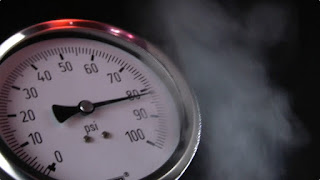
A common method for measuring hydrostatic pressure is a simple gauge. The gauge is installed at the bottom of a vessel containing a column of liquid and returns a measurement in force per unit area units, such as PSI. Gauges can also be calibrated to return measurement in units representing the height of liquid since the linear relationship between the liquid height and the pressure. The particular density of a liquid allows for a calculation of specific gravity, which expresses how dense the liquid is when compared to water. Calculating the level or depth of a column of milk in a food and beverage industry storage vessel requires the hydrostatic pressure and the density of the milk. With these values, along with some constants, the depth of the liquid can be calculated.

The liquid depth measurement can be combined with known dimensions of the holding vessel to calculate the volume of liquid in the container. One measurement is made and combined with a host of constants to determine liquid volume. The density of the liquid must be constant in order for this method to be effective. Density variation would render the hydrostatic pressure measurement unreliable, so the method is best applied to operations where the liquid density is known and constant.

Interestingly, changes in liquid density will have no effect on measurement of liquid mass as opposed to volume as long as the area of the vessel being used to store the liquid remains constant. If a liquid inside a vessel that’s partially full were to experience a temperature increase, resulting in an expansion of volume with correspondingly lower density, the transmitter will be able to still calculate the exact mass of the liquid since the increase in the physical amount of liquid is proportional to a decrease in the liquid’s density. The intersecting relationships between the process variables in hydrostatic pressure measurement demonstrate both the flexibility of process instrumentation and how consistently reliable measurements depend on a number of process related factors.

For more information on any type of pressure instrumentation, visit Ives Equipment at http://www.ivesequipment.com or call 877-768-1600.
An Explanation of Industrial Process Heating Technologies

Boiler providing steam for process heat
Boiler providing steam for process heat.
Process heating technologies can be grouped into four general categories based on the type of fuel consumed: fuel, steam, electric, and hybrid systems (which utilize a combination of energy types). These technologies are based upon conduction, convection, or radiative heat transfer mechanisms - or some combination of these. In practice, lower-temperature processes tend to use conduction or convection, whereas high-temperature processes rely primarily on radiative heat transfer. Systems using each of the four energy types can be characterized as follows:

Fuel-based process heating systems generate heat by combusting solid, liquid, or gaseous fuels, then transferring the heat directly or indirectly to the material. Hot combustion gases are either placed in direct contact with the material (i.e., direct heating via convection) or routed through radiant burner tubes or panels that rely on radiant heat transfer to keep the gases separate from the material (i.e., indirect heating).  Examples of fuel-based process heating equipment include furnaces, ovens, red heaters, kilns, melters, and high-temperature generators.

Steam-based process heating systems introduce steam to the process either directly (e.g., steam sparging) or indirectly through a heat transfer mechanism. Large quantities of latent heat from steam can be transferred efficiently at a constant temperature, useful for many process heating applications. Steam-based systems are predominantly used by industries that have a heat supply at or below about 400°F and access to low-cost fuel or byproducts for use in generating the steam. Cogeneration (simultaneous production of steam and electrical power) systems also commonly use steam-based heating systems. Examples of steam-based process heating technologies include boilers, steam spargers, steam-heated dryers, water or slurry heaters, and fluid heating systems.
Electricity-based process heating systems also transform materials through direct and indirect processes. For example, electric current is applied directly to suitable materials to achieve direct resistance heating; alternatively, high-frequency energy can be inductively coupled to suitable materials to achieve indirect heating. Electricity-based process heating systems are used for heating, drying, curing, melting, and forming. Examples of electricity-based process heating technologies include electric arc furnace technology, infrared radiation, induction heating, radio frequency drying, laser heating, and microwave processing.

Hybrid process heating systems utilize a combination of process heating technologies based on different energy sources and/or heating principles to optimize energy performance and increase overall thermal efficiency. For example, a hybrid boiler system may combine a fuel-based boiler with an electric boiler to take advantage of access to lower off-peak electricity prices. In an example of a hybrid drying system, electromagnetic energy (e.g., microwave or radio frequency) may be combined with convective hot air to accelerate drying processes; selectively targeting moisture with the penetrating electromagnetic energy can improve the speed, efficiency, and product quality as compared to a drying process based solely on convection, which can be rate-limited by the thermal conductivity of the material. Optimizing the heat transfer mechanisms in hybrid systems offers a significant opportunity to reduce energy consumption, increase speed/throughput, and improve product quality.

For more information, visit www.ivesequipment.com or call (877) 768-1600.

An Industrial Valve Positioner that Offers Decisive Advantages

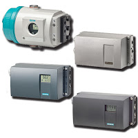
SIPART ® PS2 electro-pneumatic valve positioner
The SIPART ® PS2 electro-pneumatic valve positioner is used to control the final control element of pneumatic linear or part-turn valve actuators. The electro-pneumatic valve positioner moves the actuator to a valve position corresponding to the setpoint. Additional function inputs can be used to block the valve or to set a safety position. A binary input is present as standard in the basic device for this purpose.

The SIPART PS2 smart valve positioner is characterized by significant advantages compared to conventional devices, such as:
  • Only one device version for linear and part-turn valve actuators
  • Simple operation and programming using three keys and a two-line LCD
  • Automatic startup function with self-adjustment of zero and span
  • Manual operation without additional equipment
  • Selectable or freely-programmable characteristics
  • Minimum air consumption
  • Selectable setpoint and manipulated variable limiting
  • Programmable "tight shut-off function"
For more information about the Siemens SIPART 2 positioner download the detailed product brochure from this link,  or visit http://www.ivesequipment.com.

Upgrading to a United Electric (UE) Controls One Series from a Mechanical Pressure Switch

This video below demonstrates how to replace an older on/off mechanical pressure switch and install the UE One Series.

The One Series electronic pressure and temperature transmitter-switches set the standard for smart digital process monitoring. With a fully adjustable set point and deadband and 0.1% repeatability, the One Series performs in a wide variety of applications. Available in Type 4X enclosures approved for intrinsic safety, flameproof and non-incendive area classifications, these hybrid transmitter-switches are designed to provide transmitter, switch and gauge functions all-in-one rugged enclosure that can withstand the rigors of harsh and hazardous environments.

Each One Series model incorporates intelligent self-diagnostics and can report detected faults before they become major safety issues. Plug Port Detection protects against sensor clogging. Nuisance trip filtering reduces false and spurious signals. The ability to capture pressure spikes and valleys provides process information to aid in the commissioning and debugging process.

For more information, visit http://www.ivesequipment.com or call (877) 768-1600.

Remote Telemetry Outstation / Data Logger for Water Utilities

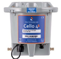
Technolog Cello 4S data logger
Technolog Cello 4S data logger.
The Technolog Cello 4S data logger monitors, records and transmits multiple site parameters over 2G (SMS/GPRS) or 3G networks, and provides a comprehensive multi-application solution for the Water Utilities and Industry.

The Cello 4S can have up to two pressure, eight user programmable digital or analogue inputs and two individually switched 12 Volt outputs for powering 4-20mA loops. Setup is made easy through an optional WiFi communication interface, and remote set-up, monitoring and control is facilitated through locally deployed PMAC software or web based WaterCore platform.
Technolog Cello 4S data logger
Technolog Cello 4S installed.

The Cello 4S provides closed loop control of pressure reducing valves, pressure sustaining valves and variable speed pumps, high accuracy battery monitoring for optimal asset management, is housed in a sturdy, portable, and waterproof to IP68 enclosure, offers 5 year battery life (typically) and includes water temperature measurement.


Or, view the specification sheet below:

Advanced Safety Integrity Universal Gas Transmitter

The Sensidyne SensAlert ASI provides enhanced protection and dependability for critical safety applications where personnel, processes, and facilities are at risk. The third-party certified SIL-2 SensAlert ASI offers dependability and versatility while remaining the easiest to install, commission, operate, and maintain.

SensAlert ASI is third-party certified to IEC61508 Level 2 (SIL-2) for both hardware and software with certification to global hazardous area and performance standards. The Test-on-Demand feature with on-board gas generator provides remote functionality checks with generated gas while Predictive Sensor End-of-Life Indication provides advanced warning of impending sensor failure.

For your convenience, we have posted the SensAlert ASI Users Manual below.

Vibrating Point Level Switch Operating Principles and Use

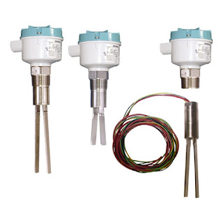
vibrating point level switch
Vibrating point level switches (SIEMENS)
When asked the primary reason to remember the year 1711, the event probably not on the minds of many is the invention of a device called the tuning fork. The tuning fork has been used as an source of resonating pitch for over three hundred years, and is still used to tune musical instruments today. While the tuning fork was initially applied to tune musical instruments, the concept of resonant frequency of a material or object has been utilized in numerous commercial, scientific, and industrial applications to provide feedback or insight into a process or operation. The vibrating fork level switch is one such industrial application where resonant frequency is used to deliver a data point or provide a control output for process operation.

The operating principle of the vibrating fork is based on the oscillating fork resonating at a known frequency in air when it is set in motion. Upon contacting a medium other than air, the resonant frequency is shifted, depending on the medium contacting or immersing the fork. Typically, fork-type level switches are installed on either the side or the top of a liquid process tank. An exciter keeps the fork oscillating, and a detector circuit monitors fork vibrating frequency, providing a change in the output signal when the frequency changes. Contact or immersion of the fork in liquid will change the fork vibrating frequency sufficiently to produce a change in output signal. Depending on the configuration of the level switch, it can function as a liquid level alarm, or provide a control output for a pump, valve, or other device. Sensor response, the change in fork vibration frequency, is a function of liquid density. Liquids with greater density will generally produce a larger frequency shift in the vibrating fork.

The wide use of vibrating level switches across various process industries is a testament to the reliability of the technology. The devices protect against overfill, indicate high and low points inside tanks, and are useful over a wide range of temperatures. A sturdy design, coupled with product variants that include a variety of sensor materials, selectable probe length, and specialized output features make vibrating fork switches applicable in many operations where level indication is needed. Chemical processing, mining, food and beverage, plastics, and other industries utilize the switches, thanks to their customizable designs and consistent performance. An advantage offered by vibrating fork level switches is a resistance to factors that sometimes confound other technologies employed for level indication. The devices will reliably function despite flow, bubbles, foam, vibration, and coating complexities related to the subject liquids. Additionally, vibrating fork switches are reliable in both high level and low level indication scenarios.

Highly viscous liquids are generally not good candidates for the application of a vibrating fork level switch. Some liquids present the potential for material accumulation between the forks, possibly resulting in poor performance. Both of these limitations are addressed by various design features incorporated by different manufacturers.

The SIEMENS SITRANS LVS200 is a vibrating point level switch for high or low levels of bulk solids. The standard LVS200 detects high, low or demand levels of dry bulk solids in bins, silos or hoppers. The liquid/solid interface version can also detect settled solids within liquids or solids within confined spaces such as feed pipes. It is designed to ignore liquids in order to detect the interface between a solid and a liquid. Additionally, the SITRANS LVS200 has an optional 4 to 20 mA output for monitoring buildup on the fork to determine when preventative maintenance should be performed in sticky applications.

For more information on any level sensing application, contact Ives Equipment by visiting http://www.ivesequipment.com of calling 877-768-1600.