What Are Industrial Control Systems?

Control systems
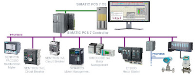
Control system diagram (click for larger view).
Control systems are computer-based systems that are used by many infrastructures and industries to monitor and control sensitive processes and physical functions. Typically, control systems collect sensor measurements and operational data from the field, process and display this information, and relay control commands to local or remote equipment. In the electric power industry they can manage and control the transmission and delivery of electric power, for example, by opening and closing circuit breakers and setting thresholds for preventive shutdowns. Employing integrated control systems, the oil and gas industry can control the refining operations on a plant site as well as remotely monitor the pressure and flow of gas pipelines and control the flow and pathways of gas transmission. In water utilities, they can remotely monitor well levels and control the wells’ pumps; monitor flows, tank levels, or pressure in storage tanks; monitor water quality characteristics, such as pH, turbidity, and chlorine residual; and control the addition of chemicals. Control system functions vary from simple to complex; they can be used to simply monitor processes—for example, the environmental conditions in a small office building—or manage most activities in a municipal water system or even a nuclear power plant.

In certain industries such as chemical and power generation, safety systems are typically implemented to mitigate a disastrous event if control and other systems fail. In addition, to guard against both physical attack and system failure, organizations may establish back-up control centers that include uninterruptible power supplies and backup generators.

Control systems
There are two primary types of control systems. Distributed Control Systems (DCS) typically are used within a single processing or generating plant or over a small geographic area. Supervisory Control and Data Acquisition (SCADA) systems typically are used for large, geographically dispersed distribution operations. A utility company may use a DCS to generate power and a SCADA system to distribute it.

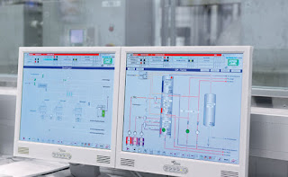
Control systemsA control system typically consists of a “master” or central supervisory control and monitoring station consisting of one or more human-machine interfaces where an operator can view status information about the remote sites and issue commands directly to the system. Typically, this station is located at a main site along with application servers and an engineering workstation that is used to configure and troubleshoot the other control system components. The supervisory control and monitoring station is typically connected to local controller stations through a hard- wired network or to remote controller stations through a communications network—which could be the Internet, a public switched telephone network, or a cable or wireless (e.g. radio, microwave, or Wi-Fi) network. Each controller station has a Remote Terminal Unit (RTU), a Programmable Logic Controller (PLC), DCS controller, or other controller that communicates with the supervisory control and monitoring station. The controller stations also include sensors and control equipment that connect directly with the working components of the infrastructure—for example, pipelines, water towers, and power lines. The sensor takes readings from the infrastructure equipment—such as water or pressure levels, electrical voltage or current—and sends a message to the controller. The controller may be programmed to determine a course of action and send a message to the control equipment instructing it what to do—for example, to turn off a valve or dispense a chemical. If the controller is not programmed to determine a course of action, the controller communicates with the supervisory control and monitoring station before sending a command back to the control equipment. The control system also can be programmed to issue alarms back to the operator when certain conditions are detected. Handheld devices, such as personal digital assistants, can be used to locally monitor controller stations. Experts report that technologies in controller stations are becoming more intelligent and automated and communicate with the supervisory central monitoring and control station less frequently, requiring less human intervention.

Contact Ives Equipment with any control systems question of challenge. Reach them by calling (877) 768-1600 or by visiting https://ivesequipment.com.
Alfa Laval Hygienic Liquid/Liquid Gasketed Plate and Frame Heat Exchanger

The following video illustrates the working principle of an Alfa Laval liquid/liquid 1-pass gasketed plate-and frame heat exchanger for use in hygienic applications. The hot liquid (shown in red) typically enters through one of the top connections and leaves through a lower connection. The cold liquid (shown in blue) enters through one of the bottom connections and leaves through the connection on top. Heat is transferred from the hot media to the cold media as the fluids pass through the heat exchanger.

The fluids enter the heat transfer plates through the connections and portholes. Highly engineered sealing gaskets between the plates direct the fluids so that the hot and cold fluids pass counter-currently in alternating channels. When the fluid enters between the plates, it passes over the distribution area.  Alfa Laval’s unique design distribution area is one of the most important features of a plate heat exchanger as it ensures an even flow of fluid over the entire plate, maximizes heat transfer efficiency, and minimizes maldistribution and fouling.

Note in the video the distribution area helps the fluids quickly fill up the entire cross section of the plates.

For very heat sensitive media, co-current flow is used in gasketed plate-and-frame heat exchangers allowing the coldest fluid meets the hottest fluid when entering the heat exchanger. This minimizes the risk of overheating or freezing sensitive media. Watching the video, imagine that the hot fluid is reversed, so that both fluids are entering at the bottom connections.

Alfa Laval has an extremely broad range of gasketed plate-and-frame heat exchangers which are used in all types of industries.

For more information about heat exchanger for use in hygienic applications contact Ives Equipment by calling (877) 768-1600 or by visiting https://www.ivesequipment.com.

Basic Information for the Design and Selection of Heat Trace Products for Pipe and Vessel Heating

Heat Tracing
Heat Tracing Self-Regulating Cable
To specify components for an effectively designed, totally electric heat trace system, it is necessary to understand the basic principles involved. A heat trace system is designed to replace heat lost through the thermal insulation from equipment in the system. In some applications, heat tracing will also be able to provide enough heat to significantly change the process temperature. 

It is always recommended to use thermal insulation since heat loss from bare surfaces is very high and heat transfer between the heater and the pipe/vessel is highly variable. All insulation should be weatherproofed. Wet insulation is ineffectual and heater output is insufficient to dry it.

There are several distinctively different types of electric heaters - self regulating, constant wattage, mineral insulated and tank heating panels. Each type has its own characteristics, often making one more suitable for a certain application than the others.


Self Regulating Heater Cable
Self Regulating Heater Cable will adjust its own output in response to pipe temperature. Available in a variety of temperature and power ratings up to 230°C (450°F) and 65.6w/m (20w/ft.). Product features include:
  • Variable Output
    • Self-Regulating heaters will react to variations in temperature encountered at every point along its length. Colder sections receive more heat output, while warmer sections receive less. This provides greater energy efficiency and more uniform pipe temperatures.
  • Can Be Overlapped Without Damage
    • Because Self-Regulating heaters controls its own output, overlapped sections produce less heat, eliminating “hot spots” and possible burn-through common with other types of cable.
  • Fail Safe
    • Upon reaching the upper limits of its temperature range, Self-Regulating heaters diminishes its own heat output to an insignificant level. This guarantees that maximum temperatures (T ratings) cannot be exceeded no matter what product is used in any application.
  • Easy Installation
    • Because of its infinite parallel path circuitry, Self-Regulating heaters can be cut to any length in the field without affecting the heat output or creating “dead zones”.
Constant-Wattage Heater Cable
Constant Wattage Heat Tracing
Constant Wattage Heat Tracing Cable

Constant Wattage Heater Cable is a parallel resistance heater that produces the same watts-per-foot of heat along its entire length.
  • EasyInstallation
    • Constant-Wattage heaters can be cut to length and terminated in the field. 
  • Economical 
    • Provides good power densities and exposure temperatures with parallel circuit cable capabilities at economical prices. Exposure Temperatures to +204°C (+400°F). Ideal for maintaining many process temperature applications. 
Mineral Insulated Heater Cable
MI Cable
MI Cable

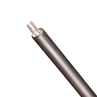
Mineral insulated Cable is a series conductor, high temperature heater cable with a special, thin metal sheath. Some of MI advantages are:
  • Corrosion-Resistant
    • Alloy 825 sheath provides excellent corrosion resistance and immunity from chloride stress corrosion - a common problem with stainless steel. 
  • Ideal for High Temperature Applications
    • Mineral Insulated heaters can withstand exposure temperatures up to 593°C (1100°F). Exposure temperatures can be increased to 750°C (1400°F) with special components. 
  • Ratings To 600V
    • Mineral Insulated heaters are available in a variety of voltages to match the available power supply. 
  • High Heat Output 
    • Mineral Insulated heaters have heat output ratings up to 10 times higher than most other cables, reducing the amount of cable required. 
  • Rugged Construction
    • A durable metal sheath provides greater mechanical protection.
  • Thin Wall Construction
    • A unique manufacturing process allows thin wall cable construction for easier field installation. 
Tank Heating Panels
Heating Panel
Heating Panel

  • Low Cost Installation
    • Flexible silicone construction allows panel to conform to tank wall. No bonding or heat transfer aids are required. 
  • High Temperature 
    • Tank Heating Panels maintain temperatures up to 79°C (175°F) and can withstand exposure to 204°C (400°F).

Happy New Year from Ives Equipment

With 2017 coming to a close, all of us at Ives Equipment wanted to reach out and send our best wishes to our customers, our vendors, and our friends! We hope that 2018 holds success and good fortune for all of you.


How New Lead-Free Regulations Will Impact Your Selection Of Potable Water Valves

Potable Water Regulations
Bottom line: Get the lead out.
Recent legislation in several states has tightened regulation of lead content in the components of potable (drinkable) water treatment systems. Other states may well be considering similar moves. This pace of regulation seems unlikely to slacken.

This report examines the choices facing specifiers and purchasers of small solenoid valves for potable water systems. It weighs the advantage and disadvantages of brass, plastic, and stainless steel designs. Finally, it suggests the solutions that smart planners should consider for current and future use.

You can download the full report (courtesy of ASCO Valve) here, or you can view it below in the embedded viewer.

Increasing Safety in Chemical Waste Water Treatment Plant

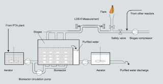
Waste water treatment and location of the measurement
Waste water treatment and location of the measurement.
Purified Terephthalic Acid (PTA) is the preferred raw material for the most common plastic products of daily life. The PTA production process generates various waste water streams which are high in organic content.

Purification of Process Waste Water

In the waste water treatment plant, the water treatment starts with aeration. The last step is an anaerobic bio reactor where the treatment is done in a controlled atmosphere. Micro organisms purify the water and produce biogas. Biogas roughly consists of 60 % methane and 40 % Carbon dioxide. This biogas is compressed and used as a fuel to reduce the net energy supply.

Although production or intrusion of oxygen into the reactors or pipes is highly unlikely, safety systems are installed. In case air enters unexpectedly into the process this first may result in a non-supporting atmosphere for the microbes and in the worst case the gas mixture may lead to an explosion.

Safety Guaranteed Using Siemens LDS 6

To ensure that oxygen never exceeds the maximum accepted concentration, the customer chose an in-situ measurement with the Siemens Laser Diode Spectrometer LDS 6. LDS 6 performs a continuous monitoring of the oxygen concentration in the biogas produced.
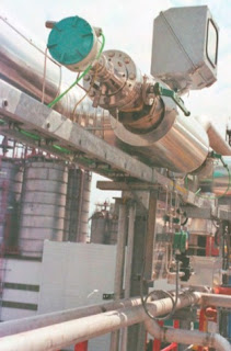
Measurement path and the two LDS 6 sensor heads
Measurement path and the
two LDS 6 sensor heads.

The response of the system is in three levels:
  1. In case the oxygen level exceeds 5 % an alarm is triggered.
  2. The threshold of 7 % causes an automatic nitrogen injection and the closure of a valve preventing the gas mixture from entering into the compressor.
  3. When the limit of 9 % is exceeded, this automatically shuts down the compressor.
The in-situ measurement leads to a fast and reliable measurement.

The stability and availability of the LDS 6 system is ensured by the integrated reference cell which provides a lifetime calibration. To be absolutely on the safe side, the customer operates a weekly safety check which involves opening a valve that allows a controlled air intake into the LDS 6 sensor heads. As the sensor heads are physically separated from the process by process windows, no oxygen may enter into the process. The reaction of the system shows in any of these tests once more the reliability of the measurement method used.

For more information about this application, or for any analytical instrument requirement, contact Ives Equipment by calling (877) 768-1600 or visiting https://www.ivesequipment.com.

Reprinted with permission from Siemens Case Study.

Beverage Container Manufacturer Improves Production Inventory Control with Radar Level Transmitter

SITRANS LR560 Radar Level Transmitter
A company in the southeastern United States produces and supplies beverage containers to a large number of bottling plants. The company produces a wide size range of polyethylene terephthalate (PET) bottles for both carbonated soft drinks and water. PET bottles are formed in a two-step process that includes both injection-molding and blow-molding equipment.

Challenge

The customer has a need to monitor the level in storage tanks containing crystallized PET plastic pellets used in the production of plastic soft drink bottles. The crystallized pellets range in density from 30 pounds per cubic feet to 56 pounds per cubic feet, and the tanks can be up to 60 feet in height.

The level measurement is used for inventory control, and it is important to maintain material supply during production periods. Production needs to know if they will need to switch tanks if the inventory is running low.

The customer had been using a plumb-bob for the level measurements and had also tried ultrasonic level measurement instruments, from a different vendor, in the past. The plumb bob cable became a mechanical nuisance, and because of high dust levels, the customer had experienced periodic loss of echo using the ultrasonic level devices.

Solution

The local Siemens representative convinced the customer to install a trial unit of the SITRANS LR560 radar level transmitter. The LR560 transmitter provided a continuous, repeatable and low-maintenance level measurement solution. The SITRANS LR560 unit’s plug and play performance is ideal for most solids level measuring applications, including those with extreme dust and high temperatures.

Its unique design allows safe and simple programming using the intrinsically-safe handheld programmer without having to open the instrument’s lid.

Results

The customer tested the trial unit for almost a year, and because of their confidence in the reliability of the level measurements, the customer placed an order for an additional 9 instruments for use in their storage silos.

Benefits

Time savings: No maintenance required. Because the SITRANS LR560 radar transmitter is a non-contacting instrument, the risk of product contamination is eliminated and no extended delays are caused as when plumb-bob cables get caught or broken.

Improved process reliability: Continuous level measurement is a real time indicator of how much is in the silo. A plumb-bob cable getting stuck at a certain distance can lead to misinterpretation of the actual level. After the cable gets stuck, there is no level history prior to the last request on demand from the instrument.

Easier to use: The SITRANS LR560 transmitter was set up using the quick start wizard and no further tuning or maintenance is required.

Unique product features: The local user interface allows for ease of con-figuration and set-up. Since the customer is only using the removable, local display during setup, the custom-er can save money by moving the display from unit to unit as needed. The narrow, 4-degree beam angle enables reliable depth penetration into the silo and ignores potential silo wall interference.

About the SITRANS LR560 Radar Level Transmitter The SITRANS LR560 2-wire, 78 GHz FMCW radar level transmitter is used for continuous monitoring of solids in silos to a range of 100 meters or 328 feet. Its plug and play performance is ideal for most solids applications, including those with extreme dust and high temperatures to +392ºF. Its unique design provides safe and simple programming using the intrinsically-safe handheld programmer without having to open the instru-ment’s lid.

The SITRANS LR560 transmitter includes an optional graphical local display interface (LDI) that improves setup and operation using an intuitive Quick Start Wizard, and echo profile display for diagnostic support. Startup is easy using the Quick Start wizard with a few parameters required for basic operation. The SITRANS LR560 instrument measures virtually any solids material level up to a range of 328 feet.

To discuss this, or any process instrument application, contact Ives Equipment by calling (877) 768-1600 or visit https://www.ivesequipment.com.