Simple Ways to Maximize the Efficiency of Your Process Control Application White Paper

Siemens Integrated Drive Systems
A white paper courtesy of SIEMENS 

No matter what industry you’re in, the price of your inputs is bound to fluctuate – usually trending in a direction that doesn’t favor profits. You can’t control the rising costs of raw materials and energy, but you can control how much you get out of them. The simplest way to do this is by maximizing the efficiency of your equipment.

Performance and productivity are directly related to energy use, reliability and maintenance costs. The improved performance offered by a highly efficient drive train helps increase output and decrease energy consumption. It also reduces wear and tear, thereby limiting maintenance costs and downtime while extending the life of your equipment. To attain this level of efficiency, one need only turn to the application-specific engineering found in integrated drive systems. 

HydroRanger 200 Customer Loyalty Offer from Siemens

HydroRanger200
Take advantage of this
offer for the HydroRanger200
Time sensitive post!

Siemens Process Industries & Drives Division is pleased to bring you the enhanced HydroRanger 200 HMI ultrasonic level controller for measurement in a wide range of industrial applications including water/wastewater monitoring and pumping, inventory management, truck load-outs, and open channel monitoring.

Enhancements include faster commissioning with an improved HMI (Human Machine Interface) and graphical Quick Start Wizards as well as a redesigned enclosure with removable terminal blocks and wider communications.

The HydroRanger 200 HMI provides high performance measurement of level, flow, differential level, and volume conversion, with additional alarm and pump control functions. Siemens’ patented Sonic Intelligence signal processing technology differentiates between true and false echoes from obstructions or electrical noise, giving users repeatable, fast, and reliable measurements.

Siemens is making it easy for you to see the benefits this instrument has to offer. As a loyal customer, they are offering you a 15% discount toward the purchase of the enhanced HydroRanger(s) 200 HMI version.

Call Ives Equipment at 877-768-1600 to place your order.
Use discount code: SPR6029
(Offer valid until December 31, 2016).

Using Magmeters in Zero Upstream and Zero Downstream Applications

MagmeterThis video provides excellent information on installing magnetic flowmeters when you do not have optimal piping situations. The video also provides the viewer with an excellent overview of how Magmeters work.

The presentation reviews topics such as how Magmeter works, mounting configuration, best practices, alternatives for when required upstream/downstream piping distances are not available, the importance of a full pipe, and what kind of accuracy you can expect in less than ideal piping situations.

For more information on magnetic flowmeters visit this link or call Ives Equipment today at (877) 768-1600.

Enhance Control System Security Using Process Switches

Process Switches
Electro-mechanical switches do not have software or an
operating system susceptible to cyber attack.
Reprinted with permission from
Untied Electric Controls

In today’s world of standardized communications, no man is an island and neither is any process control system. Networking is about to expand greatly, thanks to the increasing adoption of integrated devices, the internet, and a proliferation of open operating systems. Increasing attacks that exploit weaknesses in the network may not be far behind. Real world examples have shown that control systems can be hacked, sometimes with deadly results.

This white paper looks at how open Microsoft technology used in virtually all contemporary control systems, such as distributed control systems (DCS) and supervisory control and data acquisition (SCADA), can mean less security. The paper explores why current solutions may not be up to the task of protection. It also shows how simple, yet reliable electro-mechanical switch-based protection can improve cyber defenses by complementing traditional techniques with another layer of protection independent of centralized control systems.

Better Technology, Less Security

A long running trend is behind the increasing vulnerability of control systems to hacking and other forms of cyber mischief. Centralized control systems are typically tied together through an open network and software that is susceptible to cyber-attack. What’s more, the network extends out beyond the plant floor. Indeed, a part of the plant floor network is increasingly reaching around the world, thanks to web-based tools and interfaces.

Networking adds extra capabilities, information sharing, and lowers the cost of commercial off-the-shelf components used in process control systems. Data from a control system can be fed into enterprise management software, enabling the use of business intelligence techniques to tackle problems and improve overall performance.

However, current networked systems are more vulnerable to attack than yesterday’s stand-alone and analog-based setups. This increased susceptibility arises from expanding exposure on two fronts. First, an open standardized network that can be accessed around the world for good can also be manipulated globally for bad. Second, the more complex a network becomes, in terms of connected devices and topology, the more likely it is that some vulnerability will open up, particularly if system updates are not deployed in a timely manner.

Perhaps the best known and most complete example of this in a SCADA setting is the Stuxnet worm, which was discovered in June 2010. Stuxnet infects computers through infected USB ash drives and exploits multiple Microsoft Windows security vulnerabilities. More recently, another worm related to Stuxnet dubbed Duqu was discovered by a Budapest University. Built on the same source code as Stuxnet, Duqu may be one of many malware worms floating in cyberspace ready to attack.

An investigation by the Idaho National Laboratory demonstrated potential physical damage with a 27-ton power generator by sending conflicting instructions governing speed and other characteristics that induced the generator to literally shake apart, destroying it. In a simulation, Sandia National Laboratory engineers showed that turning o a recirculation pump while upping heat could incapacitate an entire oil refinery by simply destroying a critical component.

Current Solutions Need Improvement


Traditional solutions are not as effective as they once were. One aspect of the traditional approach is to patch software to plug vulnerabilities. Doing this prevents an attacker from gaining control of a system through the use of a trick - such as a buffer overflow overloading the software – thereby allowing an attacker free reign.

Yet another approach is to employ firewalls and intrusion detection devices to keep intruders out and prevent the exploitation of weaknesses. Very sensitive and critical control applications are further hardened through network segregation to limit points of contact to the outside world, making the systems more secure. Costly redundant components and controllers can also be used, if control applications are vital enough to warrant the extra expense.

In today’s world, unfortunately, all of these tactics can – and do – fail due to the efforts of smart savvy attackers. On the software side, the list of vulnerabilities in Linux, Windows, iOS, Android and other operating systems is long and growing. Despite the valiant efforts of the control system suppliers, attacks can succeed if an un-patched operating system or applications exist inside a trusted area due to lax system upgrades.

In addition, the growth of newer technologies, such as fieldbus networks, industrial wireless networks, and mobile hand-held devices is another potential path for hackers. The new crop of safety instrumented systems (SIS) shift from separated analog systems to digital networking architectures may be susceptible to operating system weaknesses. Wireless networks are new and even with the extraordinary security measures included in the standards, only one entry point out of an infinite amount due to ubiquitous access points through sensors and mobile devices is needed to create havoc.

In total, this situation means that the most secure approach possible – network segregation – is much less effective.

Turning to Tried and True Technology

Clearly, there is a need to add to the defense against cyber-attack. Ideally, the defense would operate in the event of a compromised control system. The solution has to be fast acting, as even small delays can lead to damaged equipment, toxic environmental exposure, loss of life, and long downtimes. It also has to be reliable, working when needed and not triggering at the wrong times. Finally, it has to be hack-proof and support current infrastructure.

Electro-mechanical process switches, a robust and proven technology, meet all of these requirements. At first glance, this is somewhat surprising since the technology is not typically considered for cyber security. However, electro-mechanical switches do not have software or an operating system susceptible to cyber attack. When properly applied, electro-mechanical switches can provide safety functions independent of a central control system. There is no processor involved, which means there is nothing to hack. Electro-mechanical switches are also fast, tripping quickly when milliseconds count. What’s more, modern implementations, like United Electric’s 100, 120 and 400 Series
of pressure and temperature switches, have virtually no false positives. When these switches trip, it is because a safe operating limit has been exceeded, dangerous conditions exist, or both.

The key to this approach is the placement of switches so that they monitor suitable process parameters. They also must be connected so that they can take the appropriate action. In the event of an out-of-limit process condition, the switches will trip. Since the switches can power relays, they can be wired so as to shut down compressors, pumps, turbines or whatever is needed to correct the situation and limit the damage.

Of course, the choice of what parameters to measure and where to do so will be dictated by the particular process in question. Likewise, what to have a switch act upon will also be process specific. They could, for example, shut o a compressor to keep a vessel from an overpressure situation or they could trip relays to take an entire plant floor offline.

To see the power of this approach, consider that one of the first actions taken in Sandia National Laboratory oil refinery attack simulation was to put the system on manual, thereby overriding automated safeguards. This hack attempt would have failed, though, given an appropriately placed and configured electro-mechanical switch. The switch would have tripped once the temperature exceeded a set point. There would be nothing the attacker could have done.

As an added bonus, switches protect against both deliberate and accidental catastrophes. After all, they do not care why a temperature limit, for example, has been exceeded. The situation could be due to malicious hacking or the failure of a pump circulating coolant. In either case, though, the switch would take the same action and provide an emergency shutdown.

Conclusion


As has been shown, increasing connectivity and automation have brought bene ts, such as diagnostics, predictive maintenance, and process optimization to process control. However, by bridging the gap between control systems and the world, these advances have also made automated control systems vulnerable to attack. Traditional solutions may not be adequate to safeguard systems in an environment where multiple, rapidly evolving technologies combine to create many potential weak links.

The solution involves a properly designed safety layer of electro-mechanical process switches to complement traditional software solutions. Switches are fast, reliable, hack-proof, and act independent of the control system. Electro-mechanical switches should be considered as the primary or redundant layer to protect critical equipment in today’s dangerous landscape. So, while no control system today may be an island, electro-mechanical switches can, in effect, provide protection from intruders before they can cause damage.
Wastewater Treatment Plants Save Big on Energy with Ultrasonic Controller

SIEMENS LUT400
SIEMENS LUT 400

For a water/wastewater treatment plant (W/WWTP), pumping is one of the most expensive parts of day-to-day operations. Varying from country to country, these costs range from 30 to 50 percent or more of a W/WWTP’s hydro bills – and in the future, this number will only increase as energy prices climb. Overall, water and wastewater treatment are one of the largest energy consumers in most municipalities, so any savings have an impact on more than just the W/WWTP.

By the Numbers

Just how much does pumping cost? Take your average 50 horsepower pump. In an hour, this pump consumes around 37 kilowatts. Do the math and at a cost of $0.065 per kilowatt hour (kWh) – Ontario, Canada’s off-peak price – that one pump costs a W/WWTP $12 every day, $4400 each year (as it has a running time of five hours per day).

But we know that many places, including Canada, the UK, Germany, South Africa, and Australia, have different rates according to the time of day or season energy is consumed. So while our single pump costs $0.065 per hour during low-energy periods, it now costs up to 80% more during Ontario’s peak-energy periods. So if the same company did all of its pumping during these peak periods, over the course of a year it would have spent an additional $3500! And remember this is just for a single pump – many W/WWTPs have hundreds of pumps, depending on a facility’s size.

Of course, no company is going to pump only in peak-energy periods – as we have just seen, that would be outrageously expensive. But, since wastewater treatment happens at all times of the day, facilities must pump during these high-cost periods.

So, How Do I Save Money?

SITRANS LUT400, Siemens’ newest ultrasonic controller, features two models that control
pump operating range
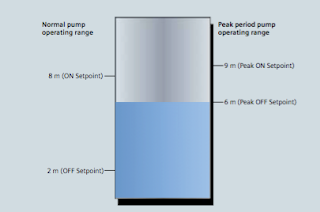
Figure 1: During peak periods, the pump operating range is
much smaller than in normal operation,
reducing the amount of time pumps must run.
economy-pumping regimes (also known as skimming): SITRANS LUT430 Level, Volume, Pump, and Flow Controller; and SITRANS LUT440 High Accuracy Open Channel Monitor, providing a full suite of advanced level, volume, and pump controls.

In normal operation, the controller will turn on pumps once water reaches the high level set point and then will begin pumping down to the low level set point. In economy pumping, the controller will pump wells down to their lowest level before the premium rate period starts, thereby maximizing the well’s storage capacity. The controller then maintains a higher level during the tariff period by using the storage capacity of the collection network. Pumping in this way ensures compliance with environmental regulations and minimizes energy use in peak tariff periods.

How Do I Set Up an Economy-pumping Regime?

Install SITRANS LUT400 ultrasonic controller and connect it to a Siemens Echomax transducer in
Siemens Echomax transducers
Siemens Echomax transducers installed in the well and the
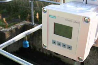
SITRANS LUT400 controller measure the level of water and
control pump operations.
your well. You will set pump on and off points based on your local peak- energy periods. During summer in Ontario, for example, the peak tariff period is between 11 a.m. and 5 p.m.

In the winter, these times change to 7-11 a.m. and 5-7 p.m. You can program up to ve peak zones during one 24-hour period.

To begin setting up your economy-pumping regime, enable SITRANS LUT400’s Energy Savings function. Set the Peak Lead Time to 60 minutes to start pumping water down 60 minutes before the high-cost period begins so the well is at its lowest point. Depending on the volume of your well, you can set your Peak Lead Time to any amount between zero and 65,535 minutes.

On the controller, select the Peak Start Time of 11:00 a.m. and the Peak End Time of 5:00 p.m. Set your Peak ON Setpoint to nine meters and the Peak OFF Setpoint to six meters, as shown in Figure 1.

In Normal Operation mode, the controller starts the pump when water reaches eight meters and stops the pump at two meters. In Energy Saving mode, SITRANS LUT400 turns on the pump when water reaches nine meters and stops pumping at six meters, thus running the pump for the minimum amount of time during peak tariff periods. Cost-savings through economy-pumping regimes are simple to put in place with these steps.

Don’t forget that when you are setting up your controller, you can take advantage of SITRANS LUT400’s real-time clock for daylight saving time adjustment. The real-time clock is a useful feature – input your location’s daylight saving time and economy pumping will occur throughout the year without interruption.

Infiltration and Ingress (I&I) Monitoring
LUT400 controller and XRS-5 transducer
in a wet well application


Another cost-saving feature of this controller is in ltra- tion and ingress monitoring with SITRANS LUT400’s pumped volume feature and built-in datalogging capabilities.

In a closed collection network, it is inef cient and costly to pump rainwater entering the system due to leakages from degraded pipes. SITRANS LUT400 calculates pumped volumes, providing useful historical trending information for detecting abnormal increases of pumped water.

To use this feature, provide the known volume in the well between the pump’s ON and OFF setpoints. The controller will calculate the pumped volume based on the rate of level change in the well during pumping. It also calculates the in ow rate based on the rate of level change in the well just prior to pump startup.

SITRANS LUT400 logs this information for you to review via the controller’s communications options, or by connect- ing a USB cable and downloading logs directly to your computer. By comparing these results, you can see if in ow rates are greater due to rainwater entering the system. Repair those damaged pipes and the cost savings begin!

Through economy pumping and I&I monitoring, SITRANS LUT400 gives companies the potential for sig- ni cant energy savings. One SITRANS LUT400 user stated that every small change his company makes to reduce consumption has the potential to save millions of dollars each year.

For more information, contact:
Ives Equipment
(877) 768-1600

Monitoring and Control of Carbon Monoxide Emissions in a Parking Structure

Parking lot CO2 Monitor
(courtesy of CONSPEC)
Reprinted with permission by CONSPEC


Carbon monoxide (CO) emissions from motor vehicles can have detrimental effects on the air quality inside subterranean parking garages. CO, an odorless, tasteless and colorless gas, is the leading cause of accidental poisoning deaths in the United States. The Centers for Disease Control estimates that CO poisoning claims nearly 500 lives and accounts for more than 15,000 visits to emergency rooms annually. When not properly ventilated, CO concentrations can build to toxic levels. Also when CO emissions fill a space, the oxygen in that space is depleted, causing asphyxiation.

In an underground parking garage without adequate ventilation, CO can easily exceed NIOSH and OSHA recommendations, and put workers, tenants and commuters at severe health and safety risks. Several states have passed laws to protect parking garage personnel from CO exposure.

Ventilation systems, therefore, are a must for today’s mixed use underground parking facilities, but they can be costly to operate 24 hours, seven days a week. This is why mechanical contractors and HVAC specialists are increasingly specifying CO monitoring and ventilations systems for both new and existing parking structures.

CARBON MONOXIDE SENSING TECHNOLOGIES

Not all CO sensors are alike. Electrochemical sensing technology provides many advantages over the older semiconductor (“solid state”) sensors or infrared sensors. Electrochemical sensors offer high resolution (≤ 0.5 ppm), a linear signal, long-term stability (≥5% over the lifetime of the sensor) and immunity to false alarms caused by “nuisance gases.”

The best CO sensing technologies will also alert facility and emergency personnel, via cell phone, in the case of dangerous concentrations of CO. Use of CO monitoring and ventilation can not only protect human health, but also can help prevent fire, as increased CO levels can sometimes predict the imminent threat of fire.

While inadequate ventilation can drastically increase the risks of liability, continuous operation of ventilation systems can
be costly. To minimize heat loss in winter, as well as conserve energy used by the ventilation fan motors, some parking garage owners began to operate ventilation systems only during peak traffic times, that is, during the morning and evening rush hours. This, however, failed to take into account instances

in which a car was left idling or parking patterns varied from the norm. This explains the growing trend toward installation of CO monitoring and ventilation control systems.

AN ALTERNATIVE TO CONTINUOUS VENTILATION

To minimize health and safety liability issues, some garage owners decided to simply run ventilation systems continuously, but this created other problems. Jeff Aiken, a project manager with Professional Mechanical Contractors, Inc., notes that continuous fan operation can mean continuous annoyance for tenants in apartments or condominiums close to fans.

“CO emissions also create tremendous liability issues,” Aiken noted, “but continuous operation is not a good solution. Installing a gas detection solves this dilemma.”

In response to the energy crisis in California in the 1980s, Conspec Controls developed a combined CO monitoring and ventilation system using electrochemical sensing technology. For maximum cost efficiency in new construction, the design should include an integrated CO monitoring and ventilation system.

The Conspec P2621 is often specified due to its large area of coverage. For instance, in a typical garage with ten-foot ceilings, one unit will cover 10,000 square feet, while competing systems require two units in the same space.