Valve Actuators: An Overview

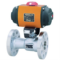
Rack & Pinion Actuated Valve
(courtesy of Flowserve Worcester)
Valves are essential to industries which constitute the backbone of the modern world. The prevalence of valves in engineering, mechanics, and science demands that each individual valve performs to a certain standard. Just as the valve itself is a key component of a larger system, the valve actuator is as important to the valve as the valve is to the industry in which it functions. Actuators are powered mechanisms that position valves between open and closed states; the actuators are controllable either by manual control or as part of an automated control loop, where the actuator responds to a remote control signal. Depending on the valve and actuator combination, valves of different types can be closed, fully open, or somewhere in-between. Current actuation technology allows for remote indication of valve position, as well as other diagnostic and operational information. Regardless of its source of power, be it electric, hydraulic, pneumatic, or another, all actuators produce either linear or rotary motion under the command of a control source.
Electric Valve Actuator
(courtesy of Flowserve Worcester)

Thanks to actuators, multiple valves can be controlled in a process system in a coordinated fashion; imagine if, in a large industrial environment, engineers had to physically adjust every valve via a hand wheel or lever! While that manual arrangement may create jobs, it is, unfortunately, completely impractical from a logistical and economic perspective. Actuators enable automation to be applied to valve operation.

Pneumatic actuators utilize air pressure as the motive force which changes the position of a valve. Pressurized-liquid reliant devices are known as hydraulic actuators. Electric actuators, either motor driven or solenoid operated, rely on electric power to drive the valve trim into position. With controllers constantly monitoring a process, evaluating inputs, changes in valve position can be remotely controlled to provide the needed response to maintain the desired process condition.

Manual valve
Manual  cryogenic ball valve
(courtesy of Flowserve Worcester)
Manual operation and regulation of valves is becoming less prevalent as automation continues to gain
traction throughout every industry. Valve actuators serve as the interface between the control intelligence and the physical movement of the valve. The timeliness and automation advantages of the valve actuators also serve as an immense help in risk mitigation, where, as long as the system is functioning correctly, critical calamities in either environmental conditions or to a facility can be pre-empted and quickly prevented. Generally speaking, manual actuators rely on hand operation of levers, gears, or wheels, but valves which are frequently changed (or which exist in remote areas) benefit from an automatic actuator with an external power source for a myriad of practical reasons, most pressingly being located in an area mostly impractical for manual operation or complicated by hazardous conditions.

Thanks to their versatility and stratified uses, actuators serve as industrial keystones to, arguably, one of the most important control elements of industries around the world. Just as industries are the backbones of societies, valves are key building blocks to industrial processes, with actuators as an invaluable device ensuring both safe and precise operation.

Contact Ives Equipment with any valve automation requirement you may have.

Basics of Variable Area Flowmeters (Rotameters)

variable area flowmeter
Rotameter
(variable area flowmeter
courtesy of SIEMENS)
Rotameters (variable area flowmeters) can be used to measure many different types of liquids and gases passing through closed piping. The robust design means that it can also be used in harsh conditions. The various types of flange connections, linings and float materials satisfy the requirements of the pharmaceutical and chemical industries.

Flow measurement is performed according to the float principle. The flowing medium lifts the conical float in the measuring ring. This increases the ring gap until an equilibrium is established between the buoyant force of the medium and the weight of the float. The height of the float is directly proportional to the flow rate. The movement of the float is transmitted from one magnet to another magnet in the display unit outside of the measuring tube.

The devices are particularly suitable for measuring:
  • Water
  • Liquids
  • Anti-corrosives and lubricants
  • Solvents
  • Saturated and superheated steam • Food and beverages
  • Industrial gases
The video below provides and excellent understanding of how rotameters operate.

Basics of Turbine Flowmeters

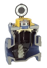
Turbine flow meter
Turbine flow meter
internal view
(courtesy of Niagara)
Turbine flowmeters are displacement devices which mechanically measure fluid flow, specifically clean liquids and gases. Turbine flowmeters, so named for the axially mounted turbine these measuring instruments employ, measure the velocity of fluids flowing through the instrument. Additional processing of the fluid velocity measurement can be used to determine volumetric and mass flow.

In a single turbine flowmeter, there is a paramagnetic bladed turbine rotator which spins proportionally to the velocity of the subject fluid flowing through the pipe. Directly above the rotator and isolated from the fluid is a pickup coil, comprised of fine wire windings and a magnet. As the fluid flows and makes the suspended rotator spin, the rotator blades pass through the magnetic field of the pickup coil, generating a sinusoidal electrical signal. This signal is processed into a final calculation of total metered volume, as well as instantaneous flow rate and mass flow, based on the counts of turbine blade passage.

Turbine flow meter
Turbine flow meter
(courtesy of Niagara)
Known for their accuracy and comparatively large turndown ratio, turbine flowmeters also accommodate a wide range of temperature and pressure combinations. Little maintenance is required and installation is generally simple to accomplish. Use of turbine flowmeters should be avoided with corrosive fluids, as well as those with high viscosity. Adequate protection, in the form of a properly sized strainer, should be provided upstream of the device. The mechanical nature of the turbine requires the support bearings to remain lubricated and in a condition that does not impede the movement of the rotor, as this would result in a reading below the actual flow rate. When applied with liquids, operators must assure that the entire cross section of the pipe in the measuring section is filled with the measured liquid.

Turbine flowmeters advantages additionally include low pressure drop and a compact design. Available sizes and materials of construction can accommodate a wide variety of applications in oil and gas, wastewater, utility, chemical, and food and beverage industries.

Proper instrument selection and configuration goes hand in hand with a proper installation toward successful project completion. Share your fluid measurement challenges with instrumentation specialists, combining your process knowledge with their product application expertise to develop effective solutions.

Municipal Wastewater Treatment: A Lighter Look

municipal wastewater treatment plant
While Disney-Pixar’s film Finding Nemo tells a fantastic story involving a father fish, his son, and the ocean, Nemo’s lucky that the plot of the film didn’t involve him being flushed down a toilet in a suburban home. If it had, Nemo would’ve undergone a crucial Odyssey before even reaching a river: he would’ve journeyed through a municipal wastewater treatment plant. While a jaunt through a municipal wastewater plant doesn’t sound as commercially attractive as adventuring through the ocean, the purity and quality of municipality waterways and their ecosystems depends on municipal wastewater plants’ implementation of standards through treatment, via an air-tight water purification process.

The goal of a municipal wastewater treatment plant is to act as a gateway between contaminated wastewater and the water sources where the wastewater eventually goes. For that reason, many wastewater treatment plants are built in low-lying areas, usually with easy to access to water sources, such as river. All the water which leaves the plant after processing, called the ‘effluent’, needs to meet a standardized level of quality. The Environmental Protection Agency (EPA) estimates that there are around 16,000 municipal treatment plants active in the U.S. today; all of them need to meet the same environmental requirements in terms of their treatment quality.

The primary treatment in the process utilized by municipal plants reduces solid objects and suspended solids in the water via a barrier – otherwise known as sedimentation. Nemo, unfortunately, probably wouldn’t’ve made it past here. The process aims to reduce the presence of solid objects, pathogenic (disease causing) bacteria, biodegradable organics (BOD’s), and excess nutrients found in the wastewater. Primary, or mechanical, treatment filters the solid objects, while secondary treatment focuses on biological elements of the water. According to the World Bank Group, 85% of BODs and associated solids are eliminated by the conclusion of secondary treatment, which correlates with the EPA’s standards and their emphasis on plants having thorough, precise, and controlled secondary treatment systems. Tertiary treatment systems are becoming more popular in plants, as the advancement of technology leads to an even more robust cleanliness demand. Especially at the tertiary level, valves are essential because computer-based instrumentation can open, close, and/or partially close valves to ensure that purification is correlating with process control.

The process controllers use level and pressure measurement instruments to evaluate the quantitative and qualitative aspects of the wastewater. The pressure and level sensors indicate that the treatment systems are functioning properly, but also that the water moves from station to station in the plant with the most efficiency and care. If the instrumentation being monitored by plant employees is incorrect, a glitch in the system could lead to a decrease in the quality of the effluent water, resulting in damage to the environment. The process technology and its controllers must be both automatically and manually sound, because reliable operators need a reliable system to produce a top-quality result.

Sorry, Nemo, the sequel isn’t taking place in a municipality anytime soon!

Seasons Greetings from Ives Equipment

Seasons Greeting from Ives Equipment
Season’s Greetings! In warm appreciation of our association during the past year, we extend our very best wishes for a happy holiday season.

Wishing you and yours the happiest of holidays and a bright and successful New Year!

Monitoring Interface Between Compounds in a Pipeline

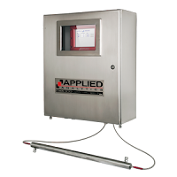
Applied Analytics™ OMA
In some cases, a single pipeline is used to transport a diverse array of chemical products. When discrete chemicals are moved sequentially through the same pipeline, a mechanical separator known as a “sealing pig” or “batching pig” is inserted between the sequential products to prevent inter-contamination.

Since the pigs are never completely effective at blocking the interface, a significant volume does suffer intermixing and must be removed for reprocessing. The amount of material routed to reprocessing is usually just pre-programmed with a large margin of error on either end of the interface to ensure removal of intermixed products. This is a simplistic model that is unnecessarily wasteful of material and time. 

By using a device such as the Applied Analytics™ OMA industrial analyzer, the chemical concentrations, purity, and physical properties can be measured in a continuously drawn sample from the liquid stream. This allows for real-time analytics of the materials in the pipe, including chemical concentrations, purity, and color. 

The OMA system continuously monitors full-spectrum absorbance in the pipeline stream. A change in this spectrum indicates a change in the purity/composition of the material passing through the pipeline. Therefore, the OMA immediately detects the ‘interface’ point where the material has begun to intermix with the subsequent material in the pipeline. 

Monitoring the 1st derivative of a complete UV-Vis/SW-NIR absorbance spectrum allows the OMA to detect changes in composition with high sensitivity and fast response. The user can define the threshold contamination level which will signal for rerouting of the stream.

For more information, contact Ives Equipment at http://www.ivesequipment.com or call (877) 768-1600.

Flow Meter for Efficient and Cost-effective Use of Water for Irrigation

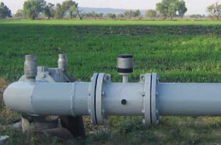
Irrigation flow meter in the field
Irrigation flow meter in the field (courtesy of SIEMENS)
Water is necessary to sustain life, but in many parts of the world it is becoming increasingly scarce. As governments enact stricter legislation in an effort to preserve this vital resource for future generations, the irrigation industry faces a formidable challenge: more carefully managing water consumption and waste prevention while still remaining profitable.

Few resources are as vital to the human population, and the global economy as water. To ensure the continuous preservation of this valuable commodity, the water industry has
On-site testing and validation via SIMATIC PDM tool. 
come to rely on accurate and reliable of battery-operated electromagnetic flow meters is part of ideal water metering solution.

Features to be considered for irrigation flow meters:
  • Battery-powered for greater flexibility in the field 
  • Accuracy
  • Maintenance-free operation 
  • Tamper-proof and robust 
  • Flexible communication 
  • Qualification certificate
  • Wireless solution
The manufacturer SIEMENS produces the SITRANS F M MAG 8000 family of battery-operated water meters providing the flexibility to install a reliable water flow meter virtually anywhere without sacrificing accuracy or performance. No main power is required. MAG 8000 complies with the custody transfer approvals MID and OIML R49 water meter standards and is specially engineered for stand-alone water applications such as abstraction, distribution network, revenue metering and irrigation.

Benefit of the SITRANS F M MAG 8000
  • Simple meter placement - floating chamber IP 68 (NEMA 6P) design ensures continuous filterless performance regardless of position or in-line piping stresses, even when buried underground 
  • Low pressure loss - unrestricted flow tube ensures minimal pressure loss even at high flow rates and reduces overall network system pressure, helping to prevent leakage from burst pipes and excess stress placed on pumping stations 
  • Zero maintenance – no moving parts and 10-year battery life 
  • Bi-directional measurement - only one meter required for measurement in both directions
  • Installation requires 0D inlet to and outlet from the sensor - eliminating concerns about where the meter is installed 
  • Intelligent meter – capable of leak detection, data logging and error self-detection 
  • Remote capabilities – stay up-to-date on measurement data without having to visit the site through optional GSM/GPRS Wireless Communication Module
For more information, contact Ives Equipment by visiting http://www.ivesequipment.com or calling (877) 768-1600.