Beverage Container Manufacturer Improves Production Inventory Control with Radar Level Transmitter

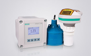
SITRANS LR560 Radar Level Transmitter
A company in the southeastern United States produces and supplies beverage containers to a large number of bottling plants. The company produces a wide size range of polyethylene terephthalate (PET) bottles for both carbonated soft drinks and water. PET bottles are formed in a two-step process that includes both injection-molding and blow-molding equipment.

Challenge

The customer has a need to monitor the level in storage tanks containing crystallized PET plastic pellets used in the production of plastic soft drink bottles. The crystallized pellets range in density from 30 pounds per cubic feet to 56 pounds per cubic feet, and the tanks can be up to 60 feet in height.

The level measurement is used for inventory control, and it is important to maintain material supply during production periods. Production needs to know if they will need to switch tanks if the inventory is running low.

The customer had been using a plumb-bob for the level measurements and had also tried ultrasonic level measurement instruments, from a different vendor, in the past. The plumb bob cable became a mechanical nuisance, and because of high dust levels, the customer had experienced periodic loss of echo using the ultrasonic level devices.

Solution

The local Siemens representative convinced the customer to install a trial unit of the SITRANS LR560 radar level transmitter. The LR560 transmitter provided a continuous, repeatable and low-maintenance level measurement solution. The SITRANS LR560 unit’s plug and play performance is ideal for most solids level measuring applications, including those with extreme dust and high temperatures.

Its unique design allows safe and simple programming using the intrinsically-safe handheld programmer without having to open the instrument’s lid.

Results

The customer tested the trial unit for almost a year, and because of their confidence in the reliability of the level measurements, the customer placed an order for an additional 9 instruments for use in their storage silos.

Benefits

Time savings: No maintenance required. Because the SITRANS LR560 radar transmitter is a non-contacting instrument, the risk of product contamination is eliminated and no extended delays are caused as when plumb-bob cables get caught or broken.

Improved process reliability: Continuous level measurement is a real time indicator of how much is in the silo. A plumb-bob cable getting stuck at a certain distance can lead to misinterpretation of the actual level. After the cable gets stuck, there is no level history prior to the last request on demand from the instrument.

Easier to use: The SITRANS LR560 transmitter was set up using the quick start wizard and no further tuning or maintenance is required.

Unique product features: The local user interface allows for ease of con-figuration and set-up. Since the customer is only using the removable, local display during setup, the custom-er can save money by moving the display from unit to unit as needed. The narrow, 4-degree beam angle enables reliable depth penetration into the silo and ignores potential silo wall interference.

About the SITRANS LR560 Radar Level Transmitter The SITRANS LR560 2-wire, 78 GHz FMCW radar level transmitter is used for continuous monitoring of solids in silos to a range of 100 meters or 328 feet. Its plug and play performance is ideal for most solids applications, including those with extreme dust and high temperatures to +392ºF. Its unique design provides safe and simple programming using the intrinsically-safe handheld programmer without having to open the instru-ment’s lid.

The SITRANS LR560 transmitter includes an optional graphical local display interface (LDI) that improves setup and operation using an intuitive Quick Start Wizard, and echo profile display for diagnostic support. Startup is easy using the Quick Start wizard with a few parameters required for basic operation. The SITRANS LR560 instrument measures virtually any solids material level up to a range of 328 feet.

To discuss this, or any process instrument application, contact Ives Equipment by calling (877) 768-1600 or visit https://www.ivesequipment.com.

Vector System Image Processor for Water in Hydrocarbons and Particles in Hydrocarbons

Canty Process Technology specializes in many refinery applications. Some applications include oil in water / water in oil, hydrogen reformer cameras, and desalter monitors. The CANTY Inflow™ is a vision-based camera system used with the CANTY Vector System image processor for water in hydrocarbons and particles in hydrocarbons in a lab environment / at-line / in-line process. The presence of these two physical contaminants is a problem for equipment the hydrocarbon is entering.

The CantyVision™ Software accurately measures multiple aspects of the hydrocarbons from water / solids / gas independent of each other for accurate data. In comparison to a laser and capacitance, which measures only one dimension and can’t identify the difference of water and solids in the stream. The CantyVision™ software can identify the differences. The customer can also visually verify the readings. 

Hydrocarbon contamination takes place mainly in production and transportation. CANTY objectively takes the measurement and reports based on a two dimensional image. Solids & water are all measured and continuously and objectively monitored. By knowing whether there is a water or solids problem this helps the operators identify how to fix the problem. The Inflow™ is an in-line analysis system to make sure production samples are not skipped over.

A brochure for the Canty Inflow™ can be downloaded here.

United Electric Controls Product Catalog

UE Champion Distributor
Ives Equipment is a
UE Champion Distributor
United Electric Controls has a rich history of over 80 years in providing protection for plant assets, people and the environment. Their pressure and temperature instrumentation is designed specifically to meet the rigors of harsh and hazardous alarm and emergency shutdown applications and includes certified safety transmitters per IEC 61508. UE, and Ives Equipment, serves the Chemical & Petrochemical, Power, Water & Wastewater and Oil & Gas industries, as well as many other challenging OEM applications.

You can download a PDF of the UE product catalog here, or view it online below.

Tried and True: Industrial Bulb and Capillary Temperature Switches

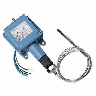
UE NEMA 4 Temperature Switch
UE watertight and corrosion resistant temperature switch.
Not all processes or operations require the use of state of the art technology to get the desired result. Part of good process design is matching up the most appropriate methods and technology to the operation.

One method of changing the state of an electrical switch from open to closed in response to a process temperature change is a bulb and capillary temperature switch.  The change in state occurs in the mechanical switch when the temperature of a process control operation crosses a certain threshold. Bulb and capillary switches have the advantage of operating without requiring an excitation voltage, simplifying their use in a given application.

The physical operating principle behind the capillary thermostat relies on the use of a fluid. The fluid inside the thermostat expands or contracts in response to the temperature at the sensing bulb. The change in fluid volume produces a force upon a diaphragm or other mechanical transfer device. The diaphragm is connected to, and changes the status of, an adjoining circuit using a snap action switch.

Because of their simplicity and comparatively modest cost, commercial versions of bulb and capillary switches find application throughout residential and commercial settings. Some common applications include warming ovens, deep fat fryers, and water heaters.

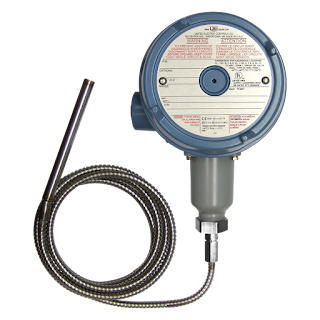
UE hazardous area temperature switch
UE hazardous area temperature switch.

Industrial versions of bulb and capillary switches are fitted with appropriate housings for the installation environment. Housings designed for hazardous areas, drenching or submersion, high dust or high corrosive environments are standardly available. Many switching options exist as well, such as high current ratings, SPDT, DPDT, dual SPDT, adjustable deadbands, and internal or external adjustments.

Operation of the temperature switches is subject to a few limitations. The setpoint is most often fixed, so changing the setpoint accurately requires trial and error or a calibration procedure. The temperature range over which the switches are suitable is comparatively limited, with a matching of the bulb and capillary fluid system to the application temperature range a necessary task in product selection. Within its proper sphere of use, though, bulb and capillary temperature switches offer simple, reliable operation, with little requirement for maintenance.

Time-tested, and application proven, these simple mechanical devices are still strong candidates for applications in any temperature control process. As with any process instrument implementation, we strongly suggest you share your application requirements with a knowledgable product specialists for the best solution.

Siemens Ultrasonic Level - How it Works

Ultrasonic level measurement
Ultrasonic level measurement is a highly cost-effective solution for short- and long-range measurement, even under difficult environmental conditions such as vibrations and dust. Ultrasonic level measurement is a non-contacting technology used in numerous industrial areas to monitor and control the level of liquids, slurries and solids.

Watch the video below for a better understanding of how this technology works.


For more information on Siemens ultrasonic level measurement, contact Ives Equipment by calling (877) 768-1600 or visiting http://www.ivesequipment.com.

The Role of a Sensor, Logic Solver and Final Element in a SIS (Safety Instrumented System)

One Series safety Transmitter
UE One Series Safety Transmitter
IEC 61511 is a technical standard which establishes practices that ensure the safety of industrial processes through the use of instrumentation. Such systems are referred to as Safety Instrumented Systems. The title of IEC 61511 is "Functional safety - Safety instrumented systems for the process industry sector".

Traditional safety systems that follow the IEC 61511 standard consists of three major components: a sensor, or a transmitter; a logic solver, or a safety PLC; and the final element, which is often a pilot valve.

Many major manufacturers provide process transmitters with safety integrity level third-party certifications to provide the industry standard for 4-20 milliamp output. This analog signal retransmits the process variable to the safety PLC for analysis where algorithms test to see if the process is within safe operating parameters. If abnormal conditions are determined to exist, an alarm may be sounded and if dangerous conditions are confirmed, an emergency shutdown sequence may be initiated.

Further exploring the roles of each of these safety system components, all three must work together flawlessly in order to bring the plan to a safe state, or allow the process to continue and run in a safe manner. Reliability of each component becomes paramount to the proper operation of the safety instrumented function, or SIP, and therefore the safe operation in the plant.

For example, the central component must continuously monitor the process variable and provide this information to the safety PLC via a hardwired connection. What actually occurs however, is the analog signal from the sensor transducer is converted to the digital domain for processing. Digital signal processing occurs inside the transmitters electronics to adjust the signal for ambient and process temperature conditions, sensor response errors, signal filtering, user settings, sensor calibration, and the process variable display. The resulting conditioned and process signals converted back to the analog domain to retransmit the 4 to 20 milliamp signal over the hardwired connection to the safety PLC. The PLC must now determine if the analog signal reveals a dangerous condition by comparing the level of the analog signal with pre-programmed set points. Here is what actually occurs. The retransmitted analog 4-20 mA signal must be converted back to the digital domain for processing inside the safety PLC's electronics. The level of the signal is compared to a pre-programmed threshold that is set at the limit of safe operation. If the signal level is determined to be within the safe limits of operation, a relay inside the safety PLC will remain closed. If the signal level is determined to be outside in the safe operating limits of the process, the safety relay will open. The safety relay state - is it open or is it closed - will determine what action the final element will take via a hardwired connection.

The final element must now take action to perform the safety function. An example of a final element is a steam cut-off valve to a turbine generator. The valve, or the final element, can quickly close to cut off the steam that passes through the generator's rotor in order to stop the rotation. Here is what actually happens. A pilot valve is connected to the plant air supply. The pilot valve is actuated by energizing 120VAC solenoid coil. When the coil is energized, the valve is held open, allowing plant air to enter the pneumatic actuator for the steam valve. Air pressure is used to hold the steam valve open allowing steam to enter, and cause the turbine generator to rotate. If the signal from the safety PLC opens to de-energize the pilot valve coil, the pilot valve will close, cutting off the air supply to the steam valve, which will cause the steam valve to close. This is an example of a de-energized to trip (or DTT) safety function.

As you can see there are a lot of components that must operate as designed to shut down the turbine generator in the event that an abnormal condition exists. Examples of abnormal conditions may include low lubrication oil pressure, high lubrication oil temperature, steam pressure that's too high, inadequate plant air pressure, etc. In order to decrease the safety instrumented functions probability to fail on-demand, all of the functions described here must work flawlessly.