United Electric Controls Product Catalog

UE Champion Distributor
Ives Equipment is a
UE Champion Distributor
United Electric Controls has a rich history of over 80 years in providing protection for plant assets, people and the environment. Their pressure and temperature instrumentation is designed specifically to meet the rigors of harsh and hazardous alarm and emergency shutdown applications and includes certified safety transmitters per IEC 61508. UE, and Ives Equipment, serves the Chemical & Petrochemical, Power, Water & Wastewater and Oil & Gas industries, as well as many other challenging OEM applications.

You can download a PDF of the UE product catalog here, or view it online below.

Tried and True: Industrial Bulb and Capillary Temperature Switches

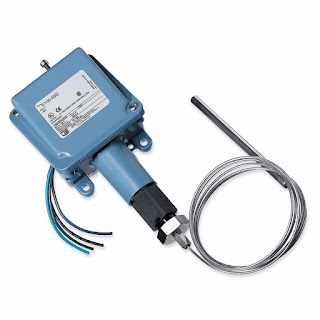
UE NEMA 4 Temperature Switch
UE watertight and corrosion resistant temperature switch.
Not all processes or operations require the use of state of the art technology to get the desired result. Part of good process design is matching up the most appropriate methods and technology to the operation.

One method of changing the state of an electrical switch from open to closed in response to a process temperature change is a bulb and capillary temperature switch.  The change in state occurs in the mechanical switch when the temperature of a process control operation crosses a certain threshold. Bulb and capillary switches have the advantage of operating without requiring an excitation voltage, simplifying their use in a given application.

The physical operating principle behind the capillary thermostat relies on the use of a fluid. The fluid inside the thermostat expands or contracts in response to the temperature at the sensing bulb. The change in fluid volume produces a force upon a diaphragm or other mechanical transfer device. The diaphragm is connected to, and changes the status of, an adjoining circuit using a snap action switch.

Because of their simplicity and comparatively modest cost, commercial versions of bulb and capillary switches find application throughout residential and commercial settings. Some common applications include warming ovens, deep fat fryers, and water heaters.

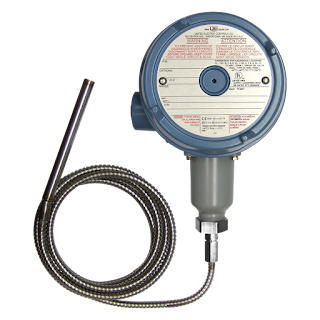
UE hazardous area temperature switch
UE hazardous area temperature switch.

Industrial versions of bulb and capillary switches are fitted with appropriate housings for the installation environment. Housings designed for hazardous areas, drenching or submersion, high dust or high corrosive environments are standardly available. Many switching options exist as well, such as high current ratings, SPDT, DPDT, dual SPDT, adjustable deadbands, and internal or external adjustments.

Operation of the temperature switches is subject to a few limitations. The setpoint is most often fixed, so changing the setpoint accurately requires trial and error or a calibration procedure. The temperature range over which the switches are suitable is comparatively limited, with a matching of the bulb and capillary fluid system to the application temperature range a necessary task in product selection. Within its proper sphere of use, though, bulb and capillary temperature switches offer simple, reliable operation, with little requirement for maintenance.

Time-tested, and application proven, these simple mechanical devices are still strong candidates for applications in any temperature control process. As with any process instrument implementation, we strongly suggest you share your application requirements with a knowledgable product specialists for the best solution.

Siemens Ultrasonic Level - How it Works

Ultrasonic level measurement
Ultrasonic level measurement is a highly cost-effective solution for short- and long-range measurement, even under difficult environmental conditions such as vibrations and dust. Ultrasonic level measurement is a non-contacting technology used in numerous industrial areas to monitor and control the level of liquids, slurries and solids.

Watch the video below for a better understanding of how this technology works.


For more information on Siemens ultrasonic level measurement, contact Ives Equipment by calling (877) 768-1600 or visiting http://www.ivesequipment.com.

The Role of a Sensor, Logic Solver and Final Element in a SIS (Safety Instrumented System)

One Series safety Transmitter
UE One Series Safety Transmitter
IEC 61511 is a technical standard which establishes practices that ensure the safety of industrial processes through the use of instrumentation. Such systems are referred to as Safety Instrumented Systems. The title of IEC 61511 is "Functional safety - Safety instrumented systems for the process industry sector".

Traditional safety systems that follow the IEC 61511 standard consists of three major components: a sensor, or a transmitter; a logic solver, or a safety PLC; and the final element, which is often a pilot valve.

Many major manufacturers provide process transmitters with safety integrity level third-party certifications to provide the industry standard for 4-20 milliamp output. This analog signal retransmits the process variable to the safety PLC for analysis where algorithms test to see if the process is within safe operating parameters. If abnormal conditions are determined to exist, an alarm may be sounded and if dangerous conditions are confirmed, an emergency shutdown sequence may be initiated.

Further exploring the roles of each of these safety system components, all three must work together flawlessly in order to bring the plan to a safe state, or allow the process to continue and run in a safe manner. Reliability of each component becomes paramount to the proper operation of the safety instrumented function, or SIP, and therefore the safe operation in the plant.

For example, the central component must continuously monitor the process variable and provide this information to the safety PLC via a hardwired connection. What actually occurs however, is the analog signal from the sensor transducer is converted to the digital domain for processing. Digital signal processing occurs inside the transmitters electronics to adjust the signal for ambient and process temperature conditions, sensor response errors, signal filtering, user settings, sensor calibration, and the process variable display. The resulting conditioned and process signals converted back to the analog domain to retransmit the 4 to 20 milliamp signal over the hardwired connection to the safety PLC. The PLC must now determine if the analog signal reveals a dangerous condition by comparing the level of the analog signal with pre-programmed set points. Here is what actually occurs. The retransmitted analog 4-20 mA signal must be converted back to the digital domain for processing inside the safety PLC's electronics. The level of the signal is compared to a pre-programmed threshold that is set at the limit of safe operation. If the signal level is determined to be within the safe limits of operation, a relay inside the safety PLC will remain closed. If the signal level is determined to be outside in the safe operating limits of the process, the safety relay will open. The safety relay state - is it open or is it closed - will determine what action the final element will take via a hardwired connection.

The final element must now take action to perform the safety function. An example of a final element is a steam cut-off valve to a turbine generator. The valve, or the final element, can quickly close to cut off the steam that passes through the generator's rotor in order to stop the rotation. Here is what actually happens. A pilot valve is connected to the plant air supply. The pilot valve is actuated by energizing 120VAC solenoid coil. When the coil is energized, the valve is held open, allowing plant air to enter the pneumatic actuator for the steam valve. Air pressure is used to hold the steam valve open allowing steam to enter, and cause the turbine generator to rotate. If the signal from the safety PLC opens to de-energize the pilot valve coil, the pilot valve will close, cutting off the air supply to the steam valve, which will cause the steam valve to close. This is an example of a de-energized to trip (or DTT) safety function.

As you can see there are a lot of components that must operate as designed to shut down the turbine generator in the event that an abnormal condition exists. Examples of abnormal conditions may include low lubrication oil pressure, high lubrication oil temperature, steam pressure that's too high, inadequate plant air pressure, etc. In order to decrease the safety instrumented functions probability to fail on-demand, all of the functions described here must work flawlessly.

Basics of Continuous Level Measurement

Continuous Level Measurement
Many industrial processes require the accurate measurement of fluid or solid (powder, granule, etc.) height within a vessel. Some process vessels hold a stratified combination of fluids, naturally separated into different layers by virtue of differing densities, where the height of the interface point between liquid layers is of interest.

A wide variety of technologies exist to measure the level of substances in a vessel, each exploiting a different principle of physics. This chapter explores the major level-measurement technologies in current use.

Level gauges (sightglasses)
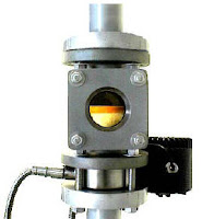
Siteglass
Siteglass


Level gauges are perhaps the simplest indicating instrument for liquid level in a vessel. They are often found in industrial level-measurement applications, even when another level-measuring instrument is present, to serve as a direct indicator for an operator to monitor in case there is doubt about the accuracy of the other instrument.

Float

Perhaps the simplest form of solid or liquid level measurement is with a float: a device that rides on the surface of the fluid or solid within the storage vessel. The float itself must be of substantially lesser density than the substance of interest, and it must not corrode or otherwise react with the substance.

Hydrostatic pressure

A vertical column of fluid generates a pressure at the bottom of the column owing to the action of gravity on that fluid. The greater the vertical height of the fluid, the greater the pressure, all other factors being equal. This principle allows us to infer the level (height) of liquid in a vessel by pressure measurement.

Displacement

Displacer level instruments exploit Archimedes’ Principle to detect liquid level by continuously measuring the weight of an object (called the displacer) immersed in the process liquid. As liquid level increases, the displacer experiences a greater buoyant force, making it appear lighter to the sensing instrument, which interprets the loss of weight as an increase in level and transmits a proportional output signal.

Echo

Echo level (radar)
Echo level (radar)
A completely different way of measuring liquid level in vessels is to bounce a traveling wave off the surface of the liquid – typically from a location at the top of the vessel – using the time-of-flight for the waves as an indicator of distance, and therefore an indicator of liquid height inside the vessel. Echo-based level instruments enjoy the distinct advantage of immunity to changes in liquid density, a factor crucial to the accurate calibration of hydrostatic and displacement level instruments. In this regard, they are quite comparable with float-based level measurement systems. Liquid-liquid interfaces may also be measured with some types of echo-based level instruments, most commonly guided-wave radar. The single most important factor to the accuracy of any echo-based level instrument is the speed at which the wave travels en route to the liquid surface and back. This wave propagation speed is as fundamental to the accuracy of an echo instrument as liquid density is to the accuracy of a hydrostatic or displacer instrument.

Weight

Weight level
Weight level measurement
Weight-based level instruments sense process level in a vessel by directly measuring the weight of the vessel. If the vessel’s empty weight (tare weight) is known, process weight becomes a simple calculation of total weight minus tare weight. Obviously, weight-based level sensors can measure both liquid and solid materials, and they have the benefit of providing inherently linear mass storage measurement. Load cells (strain gauges bonded to a steel element of precisely known modulus) are typically the primary sensing element of choice for detecting vessel weight. As the vessel’s weight changes, the load cells compress or relax on a microscopic scale, causing the strain gauges inside to change resistance. These small changes in electrical resistance become a direct indication of vessel weight.

Capacitive

Capacitive level
Capacitive level measurement
Capacitive level instruments measure electrical capacitance of a conductive rod inserted vertically
into a process vessel. As process level increases, capacitance increases between the rod and the vessel walls, causing the instrument to output a greater signal. Capacitive level probes come in two basic varieties: one for conductive liquids and one for non- conductive liquids. If the liquid in the vessel is conductive, it cannot be used as the dielectric (insulating) medium of a capacitor. Consequently, capacitive level probes designed for conductive liquids are coated with plastic or some other dielectric substance, so the metal probe forms one plate of the capacitor and the conductive liquid forms the other.

Radiation

Certain types of nuclear radiation easily penetrates the walls of industrial vessels, but is attenuated by traveling through the bulk of material stored within those vessels. By placing a radioactive source on one side of the vessel and measuring the radiation reaching the other side of the vessel, an approximate indication of level within that vessel may be obtained. Other types of radiation are scattered by process material in vessels, which means the level of process material may be sensed by sending radiation into the vessel through one wall and measuring back-scattered radiation returning through the same wall.

To download an excellent continuous level selection guide follow this link.


Content above abstracted from “Lessons In Industrial Instrumentation”
by Tony R. Kupholdt under the terms and conditions of the
Creative Commons Attribution 4.0 International Public License.

Measuring H2S in CO2 Bottling Gas

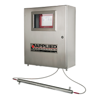
OMA H2S Analyzer
OMA H2S Analyzer 
Reprinted with permission from Applied Analytics

Prior to filling, beer bottles are purged with CO2 to remove air and protect the taste against oxidation. In the fermentation process, yeast consumes sugar and expels a large amount of CO2 which can be "reclaimed" and used for this bottle purging purpose. Unfortunately, fermentation often also produces toxic, odorous sulfides which can foam up into the piping and contaminate the reclaimed CO2.

In order to continue using the great resource of CO2 byproduct yet avoid contaminating the bottled beer with foul-smelling toxins, the reclaimed gas is run through sulfide removal skids. However, sulfide breakthrough can occur if the gas does not spend enough time in the scrubber. Employees are sometimes tasked with sniff-testing the reclaimed CO2 , but this is an unhealthy practice and is too discrete to vigilantly prevent product contamination.

An automatic, continuous analysis solution is required in order to immediately divert contaminated CO2 from use in bottling as well as provide feedback control for the sulfur removal processing time.

The OMA H2S Analyzer is used to continuously measure concentrations of hydrogen sulfide (H2S) and dimethyl sulfide (DMS) in the fermentation byproduct gas. This system uses a full-spectrum UV-Vis spectrophotometer to detect the absorbance of sulfides in the reclaimed CO2 stream, an ideal method as CO2 has zero absorbance in the UV spectrum. The OMA provides fast response alarms to high-concentration threshold which allows immediate diversion of contaminated CO2.

For this application, the OMA is typically multiplexed to automatically cycle analysis between multiple sampling points. This maximizes system value by allowing one unit to monitor the raw fermentation gas entering the reclamation system, gas coming off the acid aldehyde scrubbers, and the bottling gas coming off of the sulfur removal beds -- all with sample stream switching at user-defined intervals.

Use of Process Analyzers in Fossil Fuel Plants

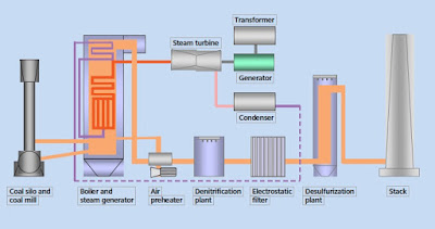
Steam Power Plant
Steam Power Plant
In spite of all efforts concerning energy savings and efficiency, the growing world population and the aspired higher 'standard of living' will lead to a further in- crease of world energy demand. In this context, almost half of the primary energy demand will continue to be covered by solid fuels, particularly by coal, until 2020 and many years beyond.

This results in the challenge to power plant engineering to implement this increasing energy demand by using new technologies and applying the highest possible conservation of the limited resources of raw materials and the environment.

This includes new materials for higher operating temperatures and, therefore, higher efficien- cies of the power plants, as well as combined power plants that drastically reduce the share of unused waste heat or improved methods for reducing emissions.

Optimizing processes without delay, designing flexible operating conditions, improved use of the load factor of new materials and safely controlling emissions of toxic substances are all tasks that require the use of powerful measurement techniques. For this purpose, devices and systems of process analytics per- form indispensable services at many locations in a power plant.

In spite of all the alternatives, the undiminished increasing world energy demand also makes the expansion of energy recovery from fossil fuels necessary. However, the use of new materials and technologies further increases the efficiency of power plants and further reduces environmental pollution from the emission of toxic substances.

In this context, process analytics plays an important role: It determines reliable and exact data from the processes and thereby allows for their optimization.

Take a moment to review the document below, or if you prefer,  download the "Use of Process Analyzers in Fossil Fuel Plants" PDF file here.