Basic Programming for the SITRANS F M Electromagnetic Flowmeter

The video below explains the basics of programming the SITRANS F M electromagnetic flowmeter.

The SITRANS F M MAG 5000 & 6000 are microprocessor-based transmitters engineered for high performance, easy installation, commissioning and maintenance. These transmitters are truly robust, cost-effective and suitable for all-round applications. The MAG 5000 has a measuring accuracy of ± 0.4% of the flow rate (incl. sensor), while the MAG 6000 has a measuring accuracy of ± 0.2% of the flow rate and can be fitted with optional plug-in communication modules.


Other Members of the SITRANS F M MAG Family:

SITRANS F M MAG 1100 is a wafer design sensor in stainless steel with highly resistant liners and electrodes and is designed for the general industry environment. The flangeless wafer design meets all flange standards. The SITRANS F M MAG 1100 is used in all industries where the corrosion-resistant stainless steel housing and the highly resistant liner and electrodes fit even the most extreme process media.

The SITRANS F M MAG 1100 F sensor is especially designed for the food & beverage and pharmaceutical industries and is available with hygienic and flexible process connections. It meets all sanitary requirements and is 3A certified and EHEDG approved.

The SITRANS F M  MAG 5100 W  with its patented liners of hard rubber NBR or ebonite and EPDM is a sensor for all water applications such as ground water, drinking water, cooling water, waste water, sewage or sludge applications.

SITRANS F M MAG 3100 is an electromagnetic flow sensor with a large variety of liners, electrode material and with grounding electrodes as standard, all this ensures a perfect fit for almost every flow application.
Also, measuring electrodes which are capable of withstanding the most extreme processes and various liners are available.

The SITRANS F M  MAG 3100 P sensor  is designed to meet the most common specifications within the chemical and process industries. It has PTFE or PFA liners and Hastelloy electrodes being the ideal combination. The fully welded construction provides a ruggedness that fits almost every flow application.

The SITRANS F M MAG 6000 I and the SITRANS F M MAG 6000 I Ex de transmitters have an measuring accuracy of + 0.2% of the flow rate and are designed to meet the demands of the process industry. Both versions are based on a microprocessor with a built-in alphanumeric display.

High Performance, Low Cost, Industrial Safety Device

Series One Safety Transmitter
Safety Transmitter
Sadly, There are too many recent examples of catastrophic industrial accidents. New safety technologies exist today that can prevent or mitigate future disasters. The philosophy of safety is changing - the focus on plant safety has changed from reactive to a proactive approach. End users have a new sense of urgency toward safety processes.

The United Electric Controls (UE) Series One is a SIL-certified (SIL stands for safety integrity level) transmitter designed solely for safety, alarm, and shutdown applications, with reliability, speed, and fewer nuisance trips. It is also designed for both greenfield and brownfield installations, and is cyber secure.

A typical safety loop consists of sensors (such as a pressure transmitter), controllers, and final control elements. Most SIL-rated pressure transmitters require 300ms to communicate with the controller and up to 500ms for the controller to send a signal to the final control element (such as a valve). This may not be fast enough for critical applications. By connecting the One Series Safety Transmitter directly connected to the final control element, the signal speed is reduced to 100ms - a huge time savings when you're in the midst of a disaster. When used with blowers, pumps and compressors, the One Series makes up a complete safety system with a self-contained sensor, controller, and final control element (the switch) capable of SIL2 without additional safety instrumented function (SIF) components.

The below document provides detailed information about the Series One.


For more information, contact:

Ives Equipment
877-768-1600
www.IvesEquipment.com


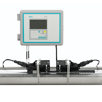
Township Water Authority Uses Ultrasonic Clamp-On Flowmeters to Avoid Surcharges for Exceeding Peak Limits

Ultrasonic Clamp-On Flowmeter
(courtesy of Siemens)
Reprinted with permission from Siemens Process Instrumentation

A suburban township buys their drinking water from a major municipal water district. The township’s water distribution system network has four connections to the larger municipality’s water transmission main. The municipality has many customers and has implemented contracts with each of its wholesale customers that limit the peak flows and the time of day in which they may occur. If the wholesale customer exceeds the limit, they are assessed significant surcharges.

Because of the potential surcharges, the wholesale customers can financially justify investing in solutions to better control their water demand, minimize the usage peaks, and control what time of day they occur. These measures include elevated water storage towers, as well as control valves at each of the connections to the municipal provider’s transmission main.

Challenge

The major municipal water district owns and operates “metering pits” with magmeters immediately upstream of the control vaults owned by each customer. However, as a rule, the signals from these meters are not made available to the any wholesale customers on a real time basis. Wholesale water customers are only given datalog summary reports from these meters on a routine schedule for billing purposes.

Without a method of measuring flows or getting flowrate data from the water district in advance, the township customer had no means of knowing, in real-time, the amount of flow they drew from the transmission main. Therefore, they did not know if or when they were exceeding the contractual peak flowrate limits and incurring significant surcharges from the water district until they were billed.

The township customer needs to know the flowrate at each of its four connections to the transmission main so they may control how much is being drawn at each site. They also need the total flow from the municipality’s transmission main, so they do not exceed their contractual peak demand.

The control vaults were initially installed without flowmeters. The intention was to use control valve position and upstream/ downstream (differential) pressure readings to estimate the flow through the control valve using the characteristic curve of the valve. This proved to be too complicated and cumbersome for their SCADA system to effectively implement.

Solution

The local Siemens representative worked with the township and their engineer to find a solution to measure the flow rate and totalize the volume of flow at each of the customer’s control vault sites. The most significant challenge was the piping configuration. All of the vaults were previously constructed without provisions for a flowmeter. The control valve vaults are very tight. The Siemens representative used a Siemens ultrasonic clamp-on flowmeter demo kit to demonstrate the technology to the customer, and prove that it would reliably meet their objectives. The vault with the worst piping configuration was selected for the demonstration. That would demonstrate that if the flowmeter would work in the worst site, it would work at the other three sites as well. However, if the Siemens flowmeter didn’t work in that site, the township would need to look at alternate, more costly, flow measurement technology for a solution. Within minutes of arriving on site, the unit was installed and providing reliable readings. The unit was allowed to log for a period of three days. After that, it was retrieved and compared to the readings from a competitive magmeter in the municipal water provider’s metering pit.

The logger on the Siemens clamp-on flowmeter provides helpful information on the quality of the velocity and flow measurements. This logged information helped establish and solidify the confidence of the owner and the engineer that the Siemens clamp-on meter would work for these applications.

Four key reasons the customer chose Siemens flowmeters:
  • The Siemens clamp-on flowmeter has the capability to make the tough measurements and provide information on the quality of those measurements. 
  • The attentive, professional and knowledgeable service they received from the local Siemens representative was well supported by Siemens personnel. 
  • The local representative provided the field service to install the transducers on the pipe, and commission the transmitters. 
  • The local representative conducted the demonstration and assisted the township engineer with their evaluation of the ultrasonic clamp-on flowmeter vs. magmeters owned by the water district. The major water district supported the Siemens ultrasonic clamp-on technology used by the township customer after they attended a Siemens Level & Flow Seminar held in their district. 
Benefits
  • Cost Savings - If they were not able to use the Siemens ultrasonic clamp-on flowmeters, the customer would have had to excavate and install a below-grade vault to house a magmeter and associated isolation and by-pass valves, along with conduit and wiring, at each of these four sites. This would have required cutting the water pipe and then going through a cumbersome disinfection process, both of which would have required lengthy permitting and costly testing. Further, some of the sites really had little or no room to accommodate such a structure or piping modifications. It is estimated these modifications would have totaled over $250,000. In comparison, the customer ended up spending $25,000 for the meters, and field service to install some conduit from the pipe to an existing above grade SCADA panel. 
  • Time Savings - The customer had already made improvements to the distribution system and installed four new control vaults. Their construction contracts were closing and they could not use their water tower until the new flow controls were added. Time was a critical factor. The customer saved 3-6 months in time by using the Siemens clamp-on flowmeters instead of having to construct new vaults to house magmeters. 
  • Improved Process Reliability - Now that the meters are in place, the customer can control how much water they are taking from the water district at each of these four locations, and ensure they do not exceed their contractual peak. They can now also properly manage the fill and draw of their elevated storage tank to offset peak demands, and fill/store during periods of low demand. 

Step-by-Step Instructions for Installing a Samson 3277 Actuator

The Samson 3277 is a pneumatic linear actuator suitable for attachment to Samson Series 240, 250, 280 and 290 control valves, as well as the type 3510 Micro-flow valves. Designed with a rolling diaphragm and internal springs, the Samson 3277 is popular because of its low overall height, fast response, low friction, and its ease to maintain. Attaching the actuator, or replacing one, can be done in minutes, without the need of special tools.


This video provide step-by-step instruction on how to install the 3277 actuator.


The Coriolis Principle and It's Use in Flow Measurement

Image courtesy of
Wikipedia
The Coriolis effect acts on a medium that is accelerated through a rotating system, like a ball on a rotating disk its movement is straight, however, if the observer turns with the disk the ball is apparently deflected (see image).

The same effect occurs with a water hose that rotates around its own axis, like a skipping rope. As soon as water flows through the host also twists. The twisting is stronger or weaker, depending on the amount of water flowing through the hose.

Coriolis flow meters function according to the same principle (measuring the force resulting from acceleration caused by mass moving toward, or away from, a center of rotation).
Oscillation with flow
(courtesy of Wikipedia)
Oscillation without flow
(courtesy of Wikipedia)
 
The Coriolis effect also appears with an oscillating movement, and in a Coriolis flowmeter, two symmetric metal tubes are set vibrating by an internal driver coil. The tubes oscillate with a resonance frequency similarly to that of a tuning fork.

The oscillation is measured precisely by two pick-ups at the inlet and outlet sections. If liquids or gases flow through the tubes, a phase shift occurs the pickups measure the spatial and temporal displacement (twist). The amount of twist is proportional to the mass flow rate of fluid passing through the tubes. The greater the amount, the stronger the tubes oscillate outwards.

Finally, sensors and transmitters are used to measure the twist and create a linear flow signal as an output for monitoring and control.

This video, although marketing oriented, does a great job illustrating the Coriolis effect and how Coriolis flowmeters measure mass flow (the video references the Siemens SITRANS FC430 as the example).


Ultrasonic Level Measurement


Ultrasonic level instruments measure the distance from the transmitter (located at some high point) to the surface of a process material located farther below using reflected sound waves. The frequency of these waves extend beyond the range of human hearing, which is why they are called ultrasonic. The time-of-flight for a sound pulse indicates this distance, and is interpreted by the transmitter electronics as process level. These transmitters may output a signal corresponding either to the fullness of the vessel (fillage) or the amount of empty space remaining at the top of a vessel (ullage).

Ullage is the “natural” mode of measurement for this sort of level instrument, because the sound wave’s time-of-flight is a direct function of how much empty space exists between the liquid surface and the top of the vessel. Total tank height will always be the sum of fillage and ullage, though. If the ultrasonic level transmitter is programmed with the vessel’s total height, it may calculate fillage via simple subtraction:

Fillage = Total height − Ullage

If a sound wave encounters a sudden change in material density, some of that wave’s energy will be reflected in the form of another wave in the opposite direction. In other words, the sound wave will “echo” when it reaches a discontinuity in density20. This is the basis of all ultrasonic ranging devices. Thus, in order for an ultrasonic level transmitter to function reliably, the difference in densities at the interface between liquid and gas must be large. Distinct interfaces of liquid and gas almost always exhibit huge differences in density, and so are relatively easy to detect using ultrasonic waves. Liquids with a heavy layer of foam floating on top are more difficult, since the foam is less dense than the liquid, but considerably denser than the gas above.

A weak echo will be generated at the interface of foam and gas, and another generated at the interface of liquid and foam, with the foam acting to scatter and dissipate much of the second echo’s energy.

The instrument itself consists of an electronics module containing all the power, computation, and signal processing circuits; plus an ultrasonic transducer to send and receive the sound waves. This transducer is typically piezoelectric in nature, being the equivalent of a very high-frequency audio speaker.

The ISA-standard designations for each component would be “LT” (level transmitter) for the electronics module and “LE” (level element) for the transducer, respectively. Even though we call the device responsible for transmitting and receiving the sound waves a transducer (in the scientific sense of the word), its function as a process instrument is to be the primary sensing element for the level measurement system, and therefore it is more properly designated a “level element” (LE).

This photograph shows a typical installation for an ultrasonic level-sensing element (LE), here sensing the level of wastewater in an open channel:


If the ultrasonic transducer is rugged enough, and the process vessel sufficiently free of sludge and other sound-damping materials accumulating at the vessel bottom, the transducer may be mounted at the bottom of the vessel, bouncing sound waves off the liquid surface through the liquid itself rather than through the vapor space. As stated previously, any significant difference in material densities is sufficient to reflect a sound wave. This being the case, it shouldn’t matter which material the incident sound wave propagates through first:

This arrangement makes fillage the natural measurement, and ullage a derived measurement (calculated by subtraction from total vessel height).

Ullage = Total height − Fillage

As mentioned previously, the calibration of an ultrasonic level transmitter depends on the speed of sound through the medium between the transducer and the interface. For top-mounted transducers, this is the speed of sound through the air (or vapor) over the liquid, since this is the medium through which the incident and reflected wave travel time is measured. For bottom-mounted transducers, this is the speed of sound through the liquid. In either case, to ensure good accuracy, one must make sure the speed of sound through the “timed” travel path remains reasonably constant (or else compensate for changes in the speed of sound through that medium by use of temperature or pressure measurements and a compensating algorithm).

For more information, check out this online document or visit Ives Equipment at www.ivesequipment.com.


(Attribution to Tony R. Kuphaldt under Creative Commons Attribution 3.0 United States License)

Introduction to Electrically Actuated Valves (Motor Operated Valve or MOVs)

electric valve actuators
Electric valve actuators for MOVs
The two most common methods of opening and closing industrial valves are by pneumatic actuators and electric actuators. This video introduces the viewer to electric valve operation.

Commonly known as "motor operated valves", or MOVs, electric operators can be fitted to any quarter-turn valve (90 deg. rotation) (such as a ball, butterfly or plug valve), or linear movement valve (such as a globe or gate valve).

Most often electric actuators are used where electric power is readily available and a pneumatic air systems are not. They are available in a variety of voltages and torque outputs for various size valves. Accessories such as limit switches, positioners, and hazardous area enclosures are available as well.