Reversing the Failure Mode of a SAMSON 3271/3277 Actuator from Fail Open to Fail Close


INSTRUCTIONS

WARNING: Actuators with preloaded springs are under tension. They can be identified by three long bolts protruding from the bottom of the actuator. These should be removed last, and installed first upon re-assembly.
  1. With the actuator removed from the valve, unscrew the nuts and bolts on the diaphragm case.
  2. Lift off the top diaphragm case.
  3. Remove the diaphragm plate assembly consisting of the diaphragm plate, diaphragm, and actuator stem from the actuator case.
  4. Remove the springs.
  5. Clamp the bottom section of the actuator stem into a vise using protective jaws, ensuring the actuator stem is not damaged.
  6. Remove the collar nut.
  7. Remove the diaphragm plate from the actuator stem, flip upside-down and place them back onto the actuator stem.
  8. Re-install the collar nut.
  9. If necessary, apply a suitable lubricant to the actuator stem.
  10. Install the diaphragm plate assembly together with the actuator stem pointing downward into the bottom diaphragm case.
  11. Place the springs onto the diaphragm plate, centering them in the intended recesses. The final actuator spring range will determine the appropriate springs to be installed.
  12. Place the top of the actuator case onto the assembly. Ensure that the air connections on the cases are correctly aligned with each other.
  13. Fasten the top and bottom diaphragm cases together using the nuts and bolts. Observe tightening torques.
ABOUT THE SAMSON 3271/3277

The Type 3271 pneumatic rolling diaphragm actuator is designed for all industrial applications. This actuator is a linear motion device ideal for valve sizes ranging from the micro-flow valves to large 20"+ globe control valves.

The Type 3277 pneumatic rolling diaphragm actuator with an integrated accessory attachment area is designed for all industrial applications. This actuator is a linear motion device ideal for valve sizes ranging from the micro-flow valves to 4" globe control valves.

The thrust force of the actuator depends on the actuator area, pneumatic supply pressure, spring stiffness, distance traveled, initial compression of the spring, the number of springs internal to the actuator, etc.

The Type 3271 and Type 3277 Pneumatic Actuators contain a rolling diaphragm and internal springs and have the following special features:
  • Low overall height
  • Powerful thrust at high stroking speed
  • Low friction
  • Various bench ranges by varying the number of springs or
  • their compression
  • No special tools required to change the bench range or to
  • reverse the direction of action (also version with handwheel)
  • Permissible operating temperatures from –60 to +120 °C
For more information on SAMSON Controls, contact Ives Equipment by calling 877-768-1600 or visiting https://ivesequipment.com.

Qualified US Navy Supplier of Valves, Instrumentation, and Analyzers

Ives Equipment, headquartered in King of Prussia, PA, is a qualified US Navy supplier of valves, instrumentation, and analyzers.

As an authorized ASCO, Worcester Valve, Niagara Meter (Venture Measurement), Siemens, and REOTEMP, Ives Equipment is registered under Cage Codes 1H855 and 6F024.

Ives Equipment provides the United State Navy with these products:
  • Manual ball valves ¼” through 2”
  • Pneumatic and electric control valves 1” through 2”
  • Flowmeters ½” through 12”
  • Solenoid valves all sizes 
  • Dual temperature elements
  • Pressure transmitters
  • Temperature transmitters
  • Boiler cameras
  • RTD assemblies
Ives Equipment products meet the following United States Military Standards:
  • MIL-STD-167 valves
  • MIL-STD-167 flow meters
  • Mil-Spec qualified high shock MIL-901D
  • MIL-SPEC Pneumatic and electric control valves
Services provided to the US Navy include:
  • Complete project management / engineering for ShipAlt and MachAlt projects.
  • Wide variety or instrumentation and valving approved to Mil Spec Mil-S-901D Grade A and Mil-STD-167-1.
  • Comprehensive solutions engineering for shipboard applications.
  • Successful shipboard engineering solutions within steam machinery, chilled water, bleed air, refrigeration HVAC, life safety.
Manufacturers:

ASCO Valve Authorized Navy Distributor - ASCO designs and manufactures quality solenoid valves to control the flow of air, gas, water, oil and steam. ASCO's Navy/Marine product line represents a select line of valves designed to meet US Navy specifications.

SIEMENS - Pressure, differential pressure, temperature and level transmitters for US Navy ships.

Worcester Valve (Division of Flowserve) - Having earned a reputation over 45 years for high performance and reliability, Worcester ball valves are installed on submarines and surface ships throughout the world. Their product range of materials includes Nickel Aluminum Bronze (NAB), Monel and Titanium.

Niagara Meters (Venture Measurement) - Niagara Meters is known for their robust and proven flow meter designs. Niagara Meters’ flow meter technology is used by the US Navy for operation on naval ships. Niagara Meters is proud to be a company built on innovation and reliability for which the brand has become known.

REOTEMP - Resistance temperature detector (RTD) assemblies used aboard US Navy ships.

Sensidyne: Flammable & Toxic Gas Detection for Pipeline & Gas Processing Plants

Industry-leading reliability, SensAlert ASI is the ideal fixed-point gas detector for critical safety applications. Flexible configurations and a simple interface provide maximum application versatility while remaining the easiest to install, commission, operate, and maintain.

Download the Flammable & Toxic Gas Detection for Pipeline & Gas Processing Plants guide book at the Ives Equipment website here.

Ives Equipment
https://ivesequipment.com
(877) 768-1600

Happy Holidays from Ives Equipment

Happy Holidays from all of us at Ives Equipment! Here's to a great 2019!


Understanding HART Communication Protocol

A technological advance introduced in the late 1980’s was HART, an acronym standing for Highway Addressable Remote Transmitter. The purpose of the HART standard was to create a way for instruments to digitally communicate with one another over the same two wires used to convey a 4-20 mA analog instrument signal. In other words, HART is a hybrid communication standard, with one variable (channel) of information communicated by the analog value of a 4-20 mA DC signal, and another channel for digital communication whereby many other variables could be communicated using pulses of current to represent binary bit values of 0 and 1. Those digital current pulses are superimposed upon the analog DC current signal, such that the same two wires carry both analog and digital data simultaneously.

Looking at a standard loop-powered (2-wire) process transmitter circuit, we see the transmitter, a DC power supply (voltage source), and usually a 250 ohm resistor to create a 1 to 5 volt signal readable by any voltage-sensing indicator, controller, or recorder:

HART Communications

The transmitter’s primary function in this circuit is to regulate current to a value representative of the measured process variable (e.g. pressure, temperature, flow, etc.) using a range of 4 to 20 mA, while the DC voltage source provides power for the transmitter to operate. Loop-powered instruments are very common in industrial instrumentation because they allow both power and (analog) data to be conveyed on the same pair of wires.

With the advent of microprocessor-based process transmitters, it became possible for instrument technicians to digitally configure parameters inside the transmitter (e.g. range values, damping values) and also query the transmitter for self-diagnostic alarms. In order to make full use of this digital functionality, though, there had to be some way to communicate digital data to and from the process transmitter over the same two wires used to convey the 4-20 mA analog signal. Otherwise, the only way to access this rich array of digital data inside the transmitter would be to connect a communicator device to some data port located on the transmitter itself, which is inconvenient due to the nature of how these transmitters are used in industry (located in dirty places, often hard to access while carrying a personal computer or other communication device).
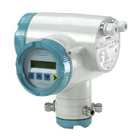
HART Transmitter
HART Transmitter
(Siemens)

Thus the HART communication protocol was born to address this need. HART communicates digital data along the loop conductors in the form of AC signals (audio-frequency tones) superimposed on the 4-20 mA DC current signal. A modem built into the smart transmitter translates these AC signals into binary bits, and vice-versa. Now, instrument technicians could “talk” with the new microprocessor-based transmitters simply by connecting a HART communications device at any point along the two-wire cable, even at the far end where the cable terminates at the control system hardware (panel-mounted controller, PLC, DCS, etc.).

Being able to communicate digital data over the same wire pair as the DC power and analog signal opens a whole new range of possibilities. Now, the field-mounted transmitter can communicate self-diagnostic information, status reports, alarms, and even multiple process variables to the control system in addition to the original analog signal representing the (main) process variable. With digital communication, the only data limitation is speed (data rate), not quantity. The control system may even communicate information to the transmitter using the same digital protocol, using this digital data channel to switch between different measurement range sets, activating special features (e.g. square-root characterization, damping, etc.), automatically and remotely.


Reprinted from "Lessons In Industrial Instrumentation" by Tony R. Kuphaldt – under the terms and conditions of the Creative Commons Attribution 4.0 International Public License.