Understanding HART Communication Protocol

A technological advance introduced in the late 1980’s was HART, an acronym standing for Highway Addressable Remote Transmitter. The purpose of the HART standard was to create a way for instruments to digitally communicate with one another over the same two wires used to convey a 4-20 mA analog instrument signal. In other words, HART is a hybrid communication standard, with one variable (channel) of information communicated by the analog value of a 4-20 mA DC signal, and another channel for digital communication whereby many other variables could be communicated using pulses of current to represent binary bit values of 0 and 1. Those digital current pulses are superimposed upon the analog DC current signal, such that the same two wires carry both analog and digital data simultaneously.

Looking at a standard loop-powered (2-wire) process transmitter circuit, we see the transmitter, a DC power supply (voltage source), and usually a 250 ohm resistor to create a 1 to 5 volt signal readable by any voltage-sensing indicator, controller, or recorder:

HART Communications

The transmitter’s primary function in this circuit is to regulate current to a value representative of the measured process variable (e.g. pressure, temperature, flow, etc.) using a range of 4 to 20 mA, while the DC voltage source provides power for the transmitter to operate. Loop-powered instruments are very common in industrial instrumentation because they allow both power and (analog) data to be conveyed on the same pair of wires.

With the advent of microprocessor-based process transmitters, it became possible for instrument technicians to digitally configure parameters inside the transmitter (e.g. range values, damping values) and also query the transmitter for self-diagnostic alarms. In order to make full use of this digital functionality, though, there had to be some way to communicate digital data to and from the process transmitter over the same two wires used to convey the 4-20 mA analog signal. Otherwise, the only way to access this rich array of digital data inside the transmitter would be to connect a communicator device to some data port located on the transmitter itself, which is inconvenient due to the nature of how these transmitters are used in industry (located in dirty places, often hard to access while carrying a personal computer or other communication device).
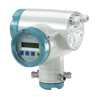
HART Transmitter
HART Transmitter
(Siemens)

Thus the HART communication protocol was born to address this need. HART communicates digital data along the loop conductors in the form of AC signals (audio-frequency tones) superimposed on the 4-20 mA DC current signal. A modem built into the smart transmitter translates these AC signals into binary bits, and vice-versa. Now, instrument technicians could “talk” with the new microprocessor-based transmitters simply by connecting a HART communications device at any point along the two-wire cable, even at the far end where the cable terminates at the control system hardware (panel-mounted controller, PLC, DCS, etc.).

Being able to communicate digital data over the same wire pair as the DC power and analog signal opens a whole new range of possibilities. Now, the field-mounted transmitter can communicate self-diagnostic information, status reports, alarms, and even multiple process variables to the control system in addition to the original analog signal representing the (main) process variable. With digital communication, the only data limitation is speed (data rate), not quantity. The control system may even communicate information to the transmitter using the same digital protocol, using this digital data channel to switch between different measurement range sets, activating special features (e.g. square-root characterization, damping, etc.), automatically and remotely.


Reprinted from "Lessons In Industrial Instrumentation" by Tony R. Kuphaldt – under the terms and conditions of the Creative Commons Attribution 4.0 International Public License.

New 2018 United Electric Controls Short Form Product Catalog

United Electric Controls is a premier manufacturer of safety, alarm, and shutdown equipment, and is a a global supplier of pressure and temperature switches, transmitters, sensors, and controls for the process, discrete, semiconductor, aerospace, and defense industries.

The UEC short form product catalog has been updated and can be downloaded here.

The Samson 3291 and 3255 Series Control Valves

Samson Controls, located in Baytown, TX, manufactures high-performance, industrial control valves designed to withstand the toughest applications.

Samson 3291
Samson 3291
Samson 3291

The Samson 3291 control valve was specifically developed for heavy duty applications in the oil and gas industry. The construction is based on the proven SAMSON valve design, with one significant difference: while the seats in SAMSON valves are normally screwed in place, the 3291 has the seat held in place by a cage retainer. Unlike typical cage guided control valves, the 3291 control valve utilizes a top and seat guided design by means of a V-port plug. This open flow-path design minimizes friction and allows for the passage of small particulates without clogging the valve or getting “trapped” between the piston and cage. To download the Samson 3291 Control Valve brochure visit this page.

The Samson 3291 Special Length Version is a direct replacement for legacy split body valves without the need for spool pieces, piping modifications, or on-site modifications.

Samson 3522 "Little Tex"

Samson 3522 "Little Tex"

The Type 3522 threaded seat control valve is designed for standard process engineering applications with high industrial requirements for control and quality. This control valve offers a wide range of trim sets to meet required flow coefficient and sealing methods as would be found in general application type control valves. The Type 3522 can be assembled with a pneumatic, electric, hydraulic, or electro-hydraulic actuator also offered by the SAMSON group to complete the control valve construction. To download the Samson 3522 Control Valve brochure visit this page.


New Flowserve Worcester Controls Industrial Valve and Actuator Catalog

The latest catalog for Flowserve Worcester Control industrial ball valves, pneumatic actuators and electric actuators, courtesy of Ives Equipment. Worcester was founded in 1955. It supplies valves throughout the world for virtually any application. These include standard flanged ball valves, ANSI and DIN specifications in reduced and full bore, three-piece valves for cryogenic, high pressure, steam, diverter or sampling duty, high integrity valves, multi-way designs, modulating controls or customized solutions.

Download a PDF version of the "Worcester Controls Industrial Valve and Actuator Catalog" here or review in the embedded document below.

Positive Displacement Flowmeters

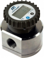
Oval Gear Flowmeter
Oval Gear Flowmeter
(Macnaught)
Positive displacement flowmeters use fluid to mechanically move internal components such as pistons, gears and discs to measure flow.  These devices are both precise and simple to operate. Unlike other liquid flow measurement technologies that rely on the measurement of a physical property of flowing media to produce a volumetric or mass flow measurement, a positive displacement flowmeter provides a direct indication of actual volumetric flow rate. There are a number of different positive displacement flowmeter designs in use throughout industrial and commercial installations:
Oscillating Piston Meter
Oscillating Piston Flowmeter
(Niagara Meter)
Each of the designs, and any others that would be classified as positive displacement, contain a mechanical structure through which the fluid must travel on its path from source to target. The fluid motion drives the mechanical assembly, which contains pathways of known volume. As the fluid motion drives the positive displacement flowmeter assembly, its rotational, oscillating, or other regular movement is counted, often by electronic means using magnetic pickups on moving assembly. The counts can be used to indicate current flow rate, or totalized to measure total flow volume. Additional inputs about fluid properties can be used to calculate mass flow, as well.

Positive displacement flowmeters can be applied to liquid or gaseous media, with the selection of the mechanical internals being a significant factor in the suitability of a design for a particular application. The longstanding use of positive displacement flowmeters across various industries has been a source of stability in terms of design, with the most recent advancements in positive displacement technology focusing on maintaining precision at lower costs.
Nutating Disc Flowmeter
(Niagara Meter)

There are a few known limitations for the use of positive displacement meters. The meters are not the optimal choice for measuring fluids with large particles, and are also non-ideal for measuring fluids with large air pockets. Additionally, systems using positive displacement meters need to account for slight pressure drops in the positive displacement meter.

Share all of your flow measurement requirements and challenges with process instrumentation experts, combining your own process knowledge and experience with their product application expertise to develop effective solutions.

Understanding Valve Positioners

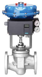
valve positioner
Valve positioner on
linear control valve
(Siemens SIPART)
Industrial valves allow the flow of a process fluid through a pipe. Valves always include some type of actuation (opening/closing) device - from simple manual levers to sophisticated electric or pneumatic actuation packages. Industrial valves can act as on/off or proportioning devices to allow full flow, no flow, or modulated flow. When valves are used for modulating fluid flow, an instrument called a valve positioner is installed.

A valve positioner is used in tandem with a valve actuator, the power source to open or close the valve. Positioners precisely direct the actuator to move the valve so that a desired flow volume is achieved and maintained. The positioner does this by monitoring the process condition, comparing it to a desired set point, and then pneumatically, electrically, or hydraulically manipulating the valve orifice until the difference between the set point and actual process variable is zero.

In closed loop control systems where the final control element are valves, valve positioners are the "brains" that provide the corrective signal to eliminate process offset. Positioners enable tighter control by overcoming the realities of valve wear, imprecise calibration, and a host of other process variable challenges.

Valve positioners are used throughout the process industries including power, pharmaceutical, chemicals, oil and gas, food and beverage, pulp and paper, refining and petrochemicals, pipelines, and many other processes.

Basic Function

positioner diagram
Diagram of typical flow control loop using valve positioner.
A valve positioner receives a signal from a controller. The controller could be part of a distributed control system (DCS), a programmable logic controller (PLC), or a discreet PID controller. The controller interprets a signal from some type of sensor, such as a flow transmitter, temperature transmitter, pressure transmitter, or other, and compares the transmitter reading to a desired setpoint. If the controller sees an offset (error), a corrective signal based on the difference, is sent to the valve positioner. The positioner then repositions the valve actuator that in turn readjusts the position of the valve, thereby changing the process condition, brining the system to to equilibrium.

Types of valve positioners:


Pneumatic Positioners

Pneumatic positioners receive pneumatic signals (3-15 or 6-30 PSIG) and proportion the supply air pressure to the valve actuator accordingly to move the valve to the required position. Pneumatic positioners are intrinsically safe and have the ability to provide a large amount of force to open or close a valve.

Electro-Pneumatic Positioners

Electro-pneumatic valve positioners are very similar to pneumatic postioners, except that they contain internal current-to-pneumatic converter (I/P). The current-to-pneumatic module receives a varying electrical signal (most commonly 4-20 mA) and converts that signal (proportionately) to a pneumatic output signal (3-15 PSIG or 6-30 PSIG). The pneumatic signal then then proportions the supply air pressure to the valve actuator.

Electric Positioners

Electric valve positioners receive an electric signal, usually 4-20 mA, 1-5 VDC, 2-10 VCD or 0-10 VDC and generally drive the motors in electric actuators. They perform the same function as pneumatic positioners do, but use electricity instead of air pressure as an input signal.

For more information on valve positioners, or any valve automation requirement, contact Ives Equipment by visiting https://ivesequipment.com or calling 877-768-1600.