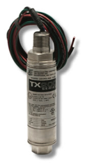
Explosion-Proof ASIC or HART Pressure Transmitter

UE TX200
UE TX200
The TX200 is a compact, rugged pressure transmitter utilizing ASIC technology to provide optimum sensor signal conditioning and temperature compensation of the sensor output. It is designed for process control industries worldwide and ideally suited for petrochemical and upstream oil and gas applications. The TX200 provides a cost-effective solution to using conventional process transmitters.

The  fixed range model TX200B is recommended for use where process pressure is consistent within the range and where physical access to the transmitter is limited or not required.

The field adjustable model TX200A allows access to zero and span the transmitter. The transmitter may be spanned up to 5:1 and for ease of calibration, does not require a calibrated pressure source and can be calibrated in-place.

Both TX200 models feature an all welded, 316 stainless steel hermetically sealed enclosure providing airtight and watertight protection within the harshest environments. A 316 stainless steel, rotatable cover protects product markings and adjustment buttons (TX200A) from the elements and tampering. The TX200 lends itself to control panel mounting or direct process mounting due to its light-weight, cylindrical design.

TX200H Hart Models

The TX200H is a HART Smart pressure transmitter that provides simplified  eld adjustment while reliably communicating asset management data utilizing the latest HART 7 specification. A proprietary calibration process insures optimum temperature compensation limiting thermal effects on the sensor output. As with the ASIC TX200, it is suited for process control industries worldwide and provides a cost-effective solution to using conventional HART transmitters.

Download the PDF cut sheet for the UE TX200 from this link or read the embedded document below.

For more information on United Electric Controls products, contact Ives Equipment by calling (877) 768-1600 or by visiting https://ivesequipment.com.

What Are Turbine Flow Meters?

Turbine Flow Meter
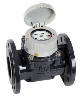
Turbine Flow Meter (Niagara WPX)
Turbine flow meters are process instruments used in a variety of industrial applications to measure the flow of a fluids. These types of flow meters operate under the simple principle that the rotation of the turbine will be constant as the turbine is acted upon by a fluid passing through the flow meter.

Turbine flow meters use the mechanical energy of the fluid to rotate a turbine blade in the flow stream and provide precise and accurate flow measurement. The flow impinging upon the turbine blades causes the rotor to spin. The angular velocity of a turbine flow meter is proportional to flow rate. The rotational velocity of the turbine is interpreted as an electrical frequency output through the use of magnetic pick-ups. As each turbine blade passes by the magnetic pick-up coil, a voltage pulse is generated which is a measure of the flow rate. The total number of pulses gives a measure of the total flow which can be totalized with a maximum error of a single pulse.

The relationship of the angle of the turbine meter blades to the flow stream governs the angular velocity and the output frequency of the meter. The sharper the angle of the turbine blade, the higher the frequency output.

Easy to maintain while also boasting reliability, turbine flow meters are known to be cost-effective solutions that make an ideal device for measuring flow rate. Aside from excellent rangeability, they also provide high response rate and high accuracy compared to other available types of flow meters. Turbine flow meters are sturdy, need very little maintenance, and seldom exhibit much deviation in performance.

These meters are used in multiple industries to reliably measure the velocity of a variety of liquids, gases and vapors over a very broad range of flow rates, temperatures, and viscosities. Turbine flow meters are used to provide measurement information in crude oil production, chemical processing, blending systems, tank storage, product off-loading, product loading, and many other applications across many industries.

Advantages
  • Simple and durable structure
  • Easy to install and maintain
  • Low pressure drop
  • Operate best in applications with fast, steadyflows
  • Operate under a wide range of temperatures and pressures
Disadvantages
  • Require straight run of pipe upstream and downstream
  • Need constant back-pressure
  • Best for lower fluid viscosity
  • Bubbles in liquids affect accuracy
  • Bearing wear
(877) 768-1600

An Exceptional Clamp- on Ultrasonic Flow Measurement Solution for Any Liquid Process

SITRANS FS230 flow system
The SITRANS FS230 digital clamp-on ultrasonic flowmeter is a process-optimizing solution for measuring flow in virtually any liquid application. Designed to provide both exceptional performance and outstanding cost savings, the FS230 is an ideal fit for many industries requiring high-quality liquid flow measurement – including water and wastewater, HVAC and power, food and beverage, pharmaceutical, chemical, mining and pulp and paper.

The SITRANS FS230 flow system consists of a SITRANS FST030 transmitter paired with SITRANS FSS200 clamp-on ultrasonic sensors, which are available in three different models: WideBeam® (High-Precision), Universal and High-Temperature.

Download the PDF from the Ives Equipment web site here, or read the document embedded below.

For more information, contact Ives by calling 877-768-1600 or by visiting https://ivesequipment.com.

SIEMENS SITRANS LR250

SITRANS LR250
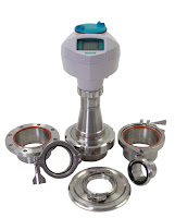
The SIEMENS SITRANS LR250 is a great choice for liquid level measurement in storage and process vessels up to 66 feet (20 meters). With a variety of antennas, the LR250 can handle a broad scope of level applications. The SITRANS LR250 flanged and hygienic encapsulated antennas mean corrosive or aggressive materials and hygienic or sanitary requirements are no challenge for this transmitter.

https://ivesequipment.com
877-768-1600


Siemens SIWAREX WT231 and WT241 Weighing Terminals

The SIWAREX WT231 and WT241  are weighing terminals for industrial use. Siemens standard components are installed in a stainless steel enclosure with numerous connection options. This ensures the tried and tested SIWAREX quality as standalone solution and is ideal for container weighers or platform scales.

SIWAREX is the optimum solution wherever strain gauge sensors, such as load cells, force sensors or torque measuring shafts, are used for measuring tasks. The typical applications of SIWAREX  are:
  • Non-automatic scales
  • Fill level monitoring of silos and bunkers
  • Measuring of crane and cable loads
  • Load measuring for industrial lifts and rolling mills
  • Force measuring, container weighers, platform scales and crane scales
SIWAREX offers the following key advantages:
  • Complete solution – no configuration in SIMATIC required
  • Fast and easy commissioning due to intuitive operating concept
  • The stainless steel enclosure permits applications in many diverse environments
  • Integrated connecting terminals for up to 4 load cells
  • Flexible connection to different systems through diverse interfaces
    • - four digital inputs
    • - four digital outputs
    • - one analog output
    • - RS 485 interface and Modbus RTU
  • High resolution of the load cell signal of up to ± 4 million parts
  • Comprehensive diagnostics functions
  • Recovery-point for the simple restoration of all parameters
  • Automatic calibration is possible without the need for calibration weights
  • All diagnostic and error messages as well as all scale parameters in plain text
  • 100-240 VAC supply range

Contact Ives Equipment by calling 877-768-1600 of by visiting https://ivesequipment.com.

Electronic Pressure Measurement: AMETEK USG Model 1536 Stainless Steel Semiconductor Pressure Gauges

Download the PDF here.

DESCRIPTION
Model 1536 Stainless Steel Semiconductor Pressure Gauge
AMETEK USG Model 1536
Stainless Steel Pressure Gauge for
Semiconductor Industry


AMETEK U.S. Gauge Model 1536 pressure gauges are designed and manufactured for gas distribution equipment used in semiconductor manufacturing. These 2 inch, all stain- less steel gauges are clean room produced, nitrogen purged, and double bagged.

These instruments are compatible with many toxic and corrosive gases. Welded face seal connections provide a threadless pressure seal and virtually eliminate a major source of contamination. Also available in NPT connections.

The Model 1536 is available in pressure ranges from 0 to 30 inches Hg VAC, to 0 to 4000 psi. This precision gauge incorporates rugged case construction with pressure relief.

FEATURES
  • Cleaning for UHP gas applications exceeding ANSI B40.100 specifications 
  • Ra: 10 μinch (0.25 μm) finish on face seal connections 
  • Helium leak tested to con rm leakage rates of less than 10-9 scc/sec. 
  • All stainless steel (Type 316L) internal surfaces for corrosion resistance 
  • Large, easy-to-read dial graduations 
  • Handles wide variety of exotic gases 
  • Available with welded face seal fittings, or NPT connection 
  • Assembled and packaged in Class 10 clean room 
  • Low mount or center back connections
SPECIFICATIONS
Close-up of VCR connection
Close-up of
VCR connection
  • Size: 2 inch diameter
  • Case: Drawn stainless steel polished with pressure relief Ring and Window: One piece, threaded polycarbonate Pointer: Aluminum, black finish.
  • Dial: Aluminum, white background with black markings Bourdon Tube: Type 316L stainless steel.
  • Connection: Type 316L stainless steel, low mount or center back mount, male or female face seal  fitting, or 1/4 inch male NPT – connectors are shipped with protective plastic caps.
  • Surface Finish:
    • Face seal connections: Ra: 10 μinch (0.25 μm) 1/4 inch NPT connections: 32 Ra.
  • Ranges: 30 inches Hg vacuum to 4000 psi, single or dual scale, see ordering information.
  • Overpressure: 130% of span maximum Working Temperature:
  • Ambient: -40°F (-40°C) to 149°F (65°C) Fluid: Maximum 212°F (100°C) Accuracy:
  • ±1% of span.
  • Scales: psi, bar, kg/cm2, KPa, MPa (single or dual scale) inches Hg (for vacuum range, compound and vacuum gauges only).

What Are Industrial Control Systems?

Control systems
Control system diagram (click for larger view).
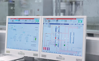
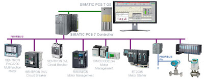
Control systems are computer-based systems that are used by many infrastructures and industries to monitor and control sensitive processes and physical functions. Typically, control systems collect sensor measurements and operational data from the field, process and display this information, and relay control commands to local or remote equipment. In the electric power industry they can manage and control the transmission and delivery of electric power, for example, by opening and closing circuit breakers and setting thresholds for preventive shutdowns. Employing integrated control systems, the oil and gas industry can control the refining operations on a plant site as well as remotely monitor the pressure and flow of gas pipelines and control the flow and pathways of gas transmission. In water utilities, they can remotely monitor well levels and control the wells’ pumps; monitor flows, tank levels, or pressure in storage tanks; monitor water quality characteristics, such as pH, turbidity, and chlorine residual; and control the addition of chemicals. Control system functions vary from simple to complex; they can be used to simply monitor processes—for example, the environmental conditions in a small office building—or manage most activities in a municipal water system or even a nuclear power plant.

In certain industries such as chemical and power generation, safety systems are typically implemented to mitigate a disastrous event if control and other systems fail. In addition, to guard against both physical attack and system failure, organizations may establish back-up control centers that include uninterruptible power supplies and backup generators.

Control systems
There are two primary types of control systems. Distributed Control Systems (DCS) typically are used within a single processing or generating plant or over a small geographic area. Supervisory Control and Data Acquisition (SCADA) systems typically are used for large, geographically dispersed distribution operations. A utility company may use a DCS to generate power and a SCADA system to distribute it.

Control systemsA control system typically consists of a “master” or central supervisory control and monitoring station consisting of one or more human-machine interfaces where an operator can view status information about the remote sites and issue commands directly to the system. Typically, this station is located at a main site along with application servers and an engineering workstation that is used to configure and troubleshoot the other control system components. The supervisory control and monitoring station is typically connected to local controller stations through a hard- wired network or to remote controller stations through a communications network—which could be the Internet, a public switched telephone network, or a cable or wireless (e.g. radio, microwave, or Wi-Fi) network. Each controller station has a Remote Terminal Unit (RTU), a Programmable Logic Controller (PLC), DCS controller, or other controller that communicates with the supervisory control and monitoring station. The controller stations also include sensors and control equipment that connect directly with the working components of the infrastructure—for example, pipelines, water towers, and power lines. The sensor takes readings from the infrastructure equipment—such as water or pressure levels, electrical voltage or current—and sends a message to the controller. The controller may be programmed to determine a course of action and send a message to the control equipment instructing it what to do—for example, to turn off a valve or dispense a chemical. If the controller is not programmed to determine a course of action, the controller communicates with the supervisory control and monitoring station before sending a command back to the control equipment. The control system also can be programmed to issue alarms back to the operator when certain conditions are detected. Handheld devices, such as personal digital assistants, can be used to locally monitor controller stations. Experts report that technologies in controller stations are becoming more intelligent and automated and communicate with the supervisory central monitoring and control station less frequently, requiring less human intervention.

Contact Ives Equipment with any control systems question of challenge. Reach them by calling (877) 768-1600 or by visiting https://ivesequipment.com.