Showing posts with label flow control. Show all posts

White Paper: Predicting Cavitation Damage in Control Valves

Cavitation can occur in control valves handling fluids, causing loud noise as well as damaging valve components and ultimately leading to additional costs in process plants. A standardized procedure to evaluate the destructiveness of cavitation-induced still does not exist whereas noise emission can reliably be predicted with the international EN 60534-8-4 standard. This white paper, courtesy of Samson Controls, describes a method to solve this problem by evaluating structure-borne noise in the ultrasonic range.

DOWNLOAD THE WHITE PAPER HERE


For more information on the application of control valves, contact Ives Equipment. Call (877) 768-1600 or visit https://ivesequipment.com.

What Are Turbine Flow Meters?

Turbine Flow Meter
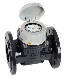
Turbine Flow Meter (Niagara WPX)
Turbine flow meters are process instruments used in a variety of industrial applications to measure the flow of a fluids. These types of flow meters operate under the simple principle that the rotation of the turbine will be constant as the turbine is acted upon by a fluid passing through the flow meter.

Turbine flow meters use the mechanical energy of the fluid to rotate a turbine blade in the flow stream and provide precise and accurate flow measurement. The flow impinging upon the turbine blades causes the rotor to spin. The angular velocity of a turbine flow meter is proportional to flow rate. The rotational velocity of the turbine is interpreted as an electrical frequency output through the use of magnetic pick-ups. As each turbine blade passes by the magnetic pick-up coil, a voltage pulse is generated which is a measure of the flow rate. The total number of pulses gives a measure of the total flow which can be totalized with a maximum error of a single pulse.

The relationship of the angle of the turbine meter blades to the flow stream governs the angular velocity and the output frequency of the meter. The sharper the angle of the turbine blade, the higher the frequency output.

Easy to maintain while also boasting reliability, turbine flow meters are known to be cost-effective solutions that make an ideal device for measuring flow rate. Aside from excellent rangeability, they also provide high response rate and high accuracy compared to other available types of flow meters. Turbine flow meters are sturdy, need very little maintenance, and seldom exhibit much deviation in performance.

These meters are used in multiple industries to reliably measure the velocity of a variety of liquids, gases and vapors over a very broad range of flow rates, temperatures, and viscosities. Turbine flow meters are used to provide measurement information in crude oil production, chemical processing, blending systems, tank storage, product off-loading, product loading, and many other applications across many industries.

Advantages
  • Simple and durable structure
  • Easy to install and maintain
  • Low pressure drop
  • Operate best in applications with fast, steadyflows
  • Operate under a wide range of temperatures and pressures
Disadvantages
  • Require straight run of pipe upstream and downstream
  • Need constant back-pressure
  • Best for lower fluid viscosity
  • Bubbles in liquids affect accuracy
  • Bearing wear
(877) 768-1600

Basics of Turbine Flowmeters

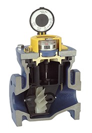
Turbine flow meter
Turbine flow meter
internal view
(courtesy of Niagara)
Turbine flowmeters are displacement devices which mechanically measure fluid flow, specifically clean liquids and gases. Turbine flowmeters, so named for the axially mounted turbine these measuring instruments employ, measure the velocity of fluids flowing through the instrument. Additional processing of the fluid velocity measurement can be used to determine volumetric and mass flow.

In a single turbine flowmeter, there is a paramagnetic bladed turbine rotator which spins proportionally to the velocity of the subject fluid flowing through the pipe. Directly above the rotator and isolated from the fluid is a pickup coil, comprised of fine wire windings and a magnet. As the fluid flows and makes the suspended rotator spin, the rotator blades pass through the magnetic field of the pickup coil, generating a sinusoidal electrical signal. This signal is processed into a final calculation of total metered volume, as well as instantaneous flow rate and mass flow, based on the counts of turbine blade passage.

Turbine flow meter
Turbine flow meter
(courtesy of Niagara)
Known for their accuracy and comparatively large turndown ratio, turbine flowmeters also accommodate a wide range of temperature and pressure combinations. Little maintenance is required and installation is generally simple to accomplish. Use of turbine flowmeters should be avoided with corrosive fluids, as well as those with high viscosity. Adequate protection, in the form of a properly sized strainer, should be provided upstream of the device. The mechanical nature of the turbine requires the support bearings to remain lubricated and in a condition that does not impede the movement of the rotor, as this would result in a reading below the actual flow rate. When applied with liquids, operators must assure that the entire cross section of the pipe in the measuring section is filled with the measured liquid.

Turbine flowmeters advantages additionally include low pressure drop and a compact design. Available sizes and materials of construction can accommodate a wide variety of applications in oil and gas, wastewater, utility, chemical, and food and beverage industries.

Proper instrument selection and configuration goes hand in hand with a proper installation toward successful project completion. Share your fluid measurement challenges with instrumentation specialists, combining your process knowledge with their product application expertise to develop effective solutions.

Using Magmeters in Zero Upstream and Zero Downstream Applications

MagmeterThis video provides excellent information on installing magnetic flowmeters when you do not have optimal piping situations. The video also provides the viewer with an excellent overview of how Magmeters work.

The presentation reviews topics such as how Magmeter works, mounting configuration, best practices, alternatives for when required upstream/downstream piping distances are not available, the importance of a full pipe, and what kind of accuracy you can expect in less than ideal piping situations.

For more information on magnetic flowmeters visit this link or call Ives Equipment today at (877) 768-1600.

Coriolis Flow Sensor with 15 RA/230 Grit for Sanitary Applications

Sanitary Coriolis flow sensor
with 15 RA / 230 Grit finish
on wetted parts.
(Courtesy of Siemens)
In sanitary applications, the finish and the material must be designed for easy and reliable cleaning and sanitation. For decades agencies have required sanitary finishes to comply to minimum standards. But now, many food, Biotech, and Pharma companies are going beyond the minimum regulations and providing high-end finishes because of the reduced sanitation time and reduced bacteria growth these finishes facilitate.

Sanitary applications mandate that stainless steel equipment have a sanitary finish. In very general terms, “sanitary finish” means a smooth, scratch-free, non-corrosive finish. But it’s much more than that. To qualify the finish more accurately, there are two primary terms used:

Roughness Average, or RA: A standard for an average of the peaks and valleys of the metal’s surface, measured in microinches or micrometers. The lower the RA, the smoother the finish.

Grit: The size of the abrasive used in the metal polishing process. Higher grit numbers are associated with higher polishing.

For process control equipment manufacturers, achieving higher-end finishes is not an easy proposition. Providing better finishes requires experience and controlled processes for quality fabrication, as well as possible tooling and production floor changes. Working inside sanitary requirements requires careful handling to prevent contamination from the manufacturing environment. Not all process instrument manufacturers are capable of providing the required environment.

A Coriolis Flowmeter with 15 RA/230 Grit for Biotech and Pharma

Siemens is currently offering a 15 RA/230 Grit surface finish for the FCS400 Coriolis flow sensor internal wetted-tube parts as a special, and will soon be offering it as a standard.

A Coriolis sensor, with such a high end finish, is very attractive to many "clean" industries including chromatography, blood plasma fractioning, chemical synthesis phases, Active Pharmaceutical Ingredient (API) extraction/fermentation and purification, formulation, and  purified API.

Biotech and Pharma manufacturers, in particular, are poised to take advantage of the enhanced 15 RA/230 Grit finish coupled with the inherent benefits of the FCS400 Coriolis flow sensor, namely:
  1. Accurate measurement across the entire range
  2. Zero internal fabrication joints and self-draining design
  3. All metal surfaces eliminate risks from particulates from the breakdown of synthetic materials
  4. No internal fluids to leak into the process
  5. A direct mass flow rate/ and total
For more information, contact:

Ives Equipment
www.ivesequipment.com
(877) 768-1600

Basics of Differential Flow Devices

Orifice plate flow meter
(courtesy of Siemens)
The differential flow meter is the most common device for measuring fluid flow through pipes. Flow rates and pressure differential of fluids, such as gases vapors and liquids, are explored using the orifice plate flow meter in the video below.

The differential flow meter, whether Venturi tube, flow nozzle, or orifice plate style, is an in line instrument that is installed between two pipe flanges.

The orifice plate flow meter is comprised the circular metal disc with a specific hole diameter that reduces the fluid flow in the pipe. Pressure taps are added on each side at the orifice plate to measure the pressure differential.

According to the Laws of Conservation of Energy, the fluid entering the pipe must equal the mass leaving the pipe during the same period of time. The velocity of the fluid leaving the orifice is greater than the velocity of the fluid entering the orifice. Applying Bernoulli's principle, the increased fluid velocity results in a decrease in pressure.

As the fluid flow rate increases through the pipe, back pressure on the incoming side increases due to the restriction of flow created by the orifice plate.

The pressure of the fluid at the downstream side at the orifice plate is less than the incoming side due to the accelerated flow.

With a known differential pressure and velocity of the fluid, the volume metric flow rate can be determined. The flow rate “Q”, of a fluid through an orifice plate increases in proportion to the square root the pressure difference on each side multiplied by the K factor. For example if the differential pressure increases by 14 PSI with the K factor of one, the flow rate is increased by 3.74.


A Clean in Place (CIP) Mag Flow Meter with Pasteurized Milk Ordinance (PMO) Approvals

magmeter with PMO approval
Magmeter with PMO approval
(courtesy of SIEMENS)
Dairies have been hampered by a limited selection of flowmeters to process raw ingredients and maximize productivity. Faced with limited choices for instrumentation, the Food and Beverage Industry is always interested in new products and certification. In this case, the product is a "Clean in Place" (CIP) electromagnetic flow meter (Magmeter) with Pasteurized Milk Ordinance (PMO) approvals.

Clean-in-place (CIP) is a method of cleaning the interior surfaces of process equipmentpipes, vessels, and fittings, without disassembly. This is an invaluable technology in the dairy, brewery, beverage, processed foods, cosmetics, and pharmaceutical industries by providing a cleaning process which is faster, far less labor-intensive, more consistent, and with less chemical exposure to workers.

The Pasteurized Milk Ordinance, is published by the Food and Drug Administration further defines minimum standards and requirements for Grade A milk production and processing.

A Magmeter is an excellent flowmeter choice for dairy use because it is unaffected by suspended solids, viscosity, and temperature challenges typically found in food and beverage applications. Additionally, magnetic flowmeters provide:
  • Ease of installation with Tri-clamp fittings.
  • Stainless steel, obstruction less flow performance meets all sanitary requirements and is 3A certified.
  • Suitable for CIP and SIP cleaning.
  • IP67 I NEMA 4X rating that is upgradeable to IP68 /NEMA 6P.
Carrying a PMO approval provides the dairy with confidence and assurance that the magnetic flowmeters have been tested and approved precisely for use in their plant.

For more information, see the document below:

Township Water Authority Uses Ultrasonic Clamp-On Flowmeters to Avoid Surcharges for Exceeding Peak Limits

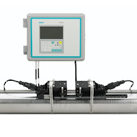
Ultrasonic Clamp-On Flowmeter
(courtesy of Siemens)
Reprinted with permission from Siemens Process Instrumentation

A suburban township buys their drinking water from a major municipal water district. The township’s water distribution system network has four connections to the larger municipality’s water transmission main. The municipality has many customers and has implemented contracts with each of its wholesale customers that limit the peak flows and the time of day in which they may occur. If the wholesale customer exceeds the limit, they are assessed significant surcharges.

Because of the potential surcharges, the wholesale customers can financially justify investing in solutions to better control their water demand, minimize the usage peaks, and control what time of day they occur. These measures include elevated water storage towers, as well as control valves at each of the connections to the municipal provider’s transmission main.

Challenge

The major municipal water district owns and operates “metering pits” with magmeters immediately upstream of the control vaults owned by each customer. However, as a rule, the signals from these meters are not made available to the any wholesale customers on a real time basis. Wholesale water customers are only given datalog summary reports from these meters on a routine schedule for billing purposes.

Without a method of measuring flows or getting flowrate data from the water district in advance, the township customer had no means of knowing, in real-time, the amount of flow they drew from the transmission main. Therefore, they did not know if or when they were exceeding the contractual peak flowrate limits and incurring significant surcharges from the water district until they were billed.

The township customer needs to know the flowrate at each of its four connections to the transmission main so they may control how much is being drawn at each site. They also need the total flow from the municipality’s transmission main, so they do not exceed their contractual peak demand.

The control vaults were initially installed without flowmeters. The intention was to use control valve position and upstream/ downstream (differential) pressure readings to estimate the flow through the control valve using the characteristic curve of the valve. This proved to be too complicated and cumbersome for their SCADA system to effectively implement.

Solution

The local Siemens representative worked with the township and their engineer to find a solution to measure the flow rate and totalize the volume of flow at each of the customer’s control vault sites. The most significant challenge was the piping configuration. All of the vaults were previously constructed without provisions for a flowmeter. The control valve vaults are very tight. The Siemens representative used a Siemens ultrasonic clamp-on flowmeter demo kit to demonstrate the technology to the customer, and prove that it would reliably meet their objectives. The vault with the worst piping configuration was selected for the demonstration. That would demonstrate that if the flowmeter would work in the worst site, it would work at the other three sites as well. However, if the Siemens flowmeter didn’t work in that site, the township would need to look at alternate, more costly, flow measurement technology for a solution. Within minutes of arriving on site, the unit was installed and providing reliable readings. The unit was allowed to log for a period of three days. After that, it was retrieved and compared to the readings from a competitive magmeter in the municipal water provider’s metering pit.

The logger on the Siemens clamp-on flowmeter provides helpful information on the quality of the velocity and flow measurements. This logged information helped establish and solidify the confidence of the owner and the engineer that the Siemens clamp-on meter would work for these applications.

Four key reasons the customer chose Siemens flowmeters:
  • The Siemens clamp-on flowmeter has the capability to make the tough measurements and provide information on the quality of those measurements. 
  • The attentive, professional and knowledgeable service they received from the local Siemens representative was well supported by Siemens personnel. 
  • The local representative provided the field service to install the transducers on the pipe, and commission the transmitters. 
  • The local representative conducted the demonstration and assisted the township engineer with their evaluation of the ultrasonic clamp-on flowmeter vs. magmeters owned by the water district. The major water district supported the Siemens ultrasonic clamp-on technology used by the township customer after they attended a Siemens Level & Flow Seminar held in their district. 
Benefits
  • Cost Savings - If they were not able to use the Siemens ultrasonic clamp-on flowmeters, the customer would have had to excavate and install a below-grade vault to house a magmeter and associated isolation and by-pass valves, along with conduit and wiring, at each of these four sites. This would have required cutting the water pipe and then going through a cumbersome disinfection process, both of which would have required lengthy permitting and costly testing. Further, some of the sites really had little or no room to accommodate such a structure or piping modifications. It is estimated these modifications would have totaled over $250,000. In comparison, the customer ended up spending $25,000 for the meters, and field service to install some conduit from the pipe to an existing above grade SCADA panel. 
  • Time Savings - The customer had already made improvements to the distribution system and installed four new control vaults. Their construction contracts were closing and they could not use their water tower until the new flow controls were added. Time was a critical factor. The customer saved 3-6 months in time by using the Siemens clamp-on flowmeters instead of having to construct new vaults to house magmeters. 
  • Improved Process Reliability - Now that the meters are in place, the customer can control how much water they are taking from the water district at each of these four locations, and ensure they do not exceed their contractual peak. They can now also properly manage the fill and draw of their elevated storage tank to offset peak demands, and fill/store during periods of low demand. 

The Coriolis Principle and It's Use in Flow Measurement

Image courtesy of
Wikipedia
The Coriolis effect acts on a medium that is accelerated through a rotating system, like a ball on a rotating disk its movement is straight, however, if the observer turns with the disk the ball is apparently deflected (see image).

The same effect occurs with a water hose that rotates around its own axis, like a skipping rope. As soon as water flows through the host also twists. The twisting is stronger or weaker, depending on the amount of water flowing through the hose.

Coriolis flow meters function according to the same principle (measuring the force resulting from acceleration caused by mass moving toward, or away from, a center of rotation).
Oscillation with flow
(courtesy of Wikipedia)
Oscillation without flow
(courtesy of Wikipedia)
 
The Coriolis effect also appears with an oscillating movement, and in a Coriolis flowmeter, two symmetric metal tubes are set vibrating by an internal driver coil. The tubes oscillate with a resonance frequency similarly to that of a tuning fork.

The oscillation is measured precisely by two pick-ups at the inlet and outlet sections. If liquids or gases flow through the tubes, a phase shift occurs the pickups measure the spatial and temporal displacement (twist). The amount of twist is proportional to the mass flow rate of fluid passing through the tubes. The greater the amount, the stronger the tubes oscillate outwards.

Finally, sensors and transmitters are used to measure the twist and create a linear flow signal as an output for monitoring and control.

This video, although marketing oriented, does a great job illustrating the Coriolis effect and how Coriolis flowmeters measure mass flow (the video references the Siemens SITRANS FC430 as the example).