- Greater accuracy: Electronic switches use electronic sensing elements, which are more accurate than mechanical ones.
- Faster response time: Electronic switches can respond much faster to changes in pressure or temperature than mechanical switches.
- Greater durability: Electronic switches have no moving parts, so they are less likely to wear out or fail.
- Increased flexibility: Electronic switches can be programmed to perform a variety of functions and are easily integrated with other electronic devices.
- Lower maintenance: Electronic switches require less maintenance than mechanical switches, as they have no moving parts to wear out.
- Greater control: Electronic switches can be programmed for various set points and output multiple signals.
- Cost Savings: Electronic switches are generally less expensive over their lifetime because of their durability and lower maintenance requirements.
Educational information on process control, industrial instrumentation, valves, valve automation and control valves. For additional information visit IvesEquipment.com or call 877-768-1600
Electronic Pressure and Temperature Switches
How Often Should You Calibrate Your Toxic/Flammable Gas Detector?
When we think of gas detector calibration and how often it must be performed, it is dependent on many variables. First and foremost is determining if a gas sensor is out of calibration.
The best way to establish this is through a “bump” or functional test using a certified standard gas mixture of known concentration. If the device is functioning properly and still measuring gas within tolerance, calibration is unnecessary. Bump testing should be performed as regular maintenance on any gas detector. With the frequency depending on the sensor technology, manufacturer recommendations, specific company standard operating procedures and environment.
The two most common sensor types are NDIR and Electrochemical.
NDIR sensors tend not to drift and are calibrated prior to shipment. They require a bump testing frequency of 6 months or less to ensure performance is consistent. Calibration is only necessary if bump testing indicates the sensor is out of specification. Electrochemical sensors tend to drift over time and require bump testing every 3 to 6 months. Calibration is recommended annually or if bump testing indicates an out of spec sensor.
Due to the technology of electrochemical sensors, they will deplete over time and more rapidly if exposed to the target gas. They can also be poisoned if exposed to certain gases. If this is a risk, then bump testing more frequently is prudent. Calibration frequency can also be dependent on gas detector relevance. If it is a portable device, then it is pragmatic to bench calibrate before utilizing it in the field. If an area is planned to have significant traffic or work, then calibration should be performed for this event.
The sensor technology industry is constantly evolving, and with that newer sensors are assuring longer periods between calibration, or potentially no need to calibrate at all.
Using newly developed materials and software, sensors may last thousands of cycles without any performance decay, even if exposed to extreme environments or chemicals. The future is markedly promising.
Remember, the most important reason to calibrate your Vanguard Gas Detector is to provide accurate gas concentration readings in order that it could prevent illness, injury or death to personnel in the area. Your Vanguard may be exposed to extreme environments such as high or low temperatures, high or low humidity, or even harsh chemicals that may require more frequent calibration. With proper maintenance, your Vanguard can provide the safety your team deserves.
For more information about fixed toxic and flammable gas detection systems contact Ives Equipment. Call them at (877) 768-1600 or visit their website at https://ivesequipment.com.
Basics of Thermocouple Junction Design
 |
| Industrial thermocouples (AST) |
A thermocouple has three variations of sensing tip (or junction):
- Exposed junction, where the exposed wire tips and welded bead have no covering or protection.
- Grounded junction, where the welded bead is in physical contact with the thermocouple's sheath.
- Ungrounded junction, where the tip is inside the thermocouple sheath, but is electrical (and somewhat thermally) insulated from the sheath (no sheath contact).
Grounded junction thermocouples provide fast response and are mechanically more robust, with a metallic sheath that protects the thermocouple both mechanically and from contaminants. But because their sensing tip is in contact with the external sheath, their signal still can be affected by externally induced or conducted electrical noise.
Ungrounded thermocouples, like grounded, are protected mechanically and from ambient contaminants by their sheath. However, their sensing junctions are kept separate from their metallic sheath, isolating the junction from external electrical interference. This separation does come at a small cost in temperature sensing responsiveness though.
For safety, precision, and optimum performance, always talk to an applications specialist when applying temperature sensors. A short phone call can prevent major headaches and lost time in troubleshooting a misapplied thermocouple.
Explosion-Proof ASIC or HART Pressure Transmitter
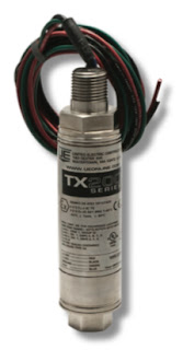 |
| UE TX200 |
The fixed range model TX200B is recommended for use where process pressure is consistent within the range and where physical access to the transmitter is limited or not required.
The field adjustable model TX200A allows access to zero and span the transmitter. The transmitter may be spanned up to 5:1 and for ease of calibration, does not require a calibrated pressure source and can be calibrated in-place.
Both TX200 models feature an all welded, 316 stainless steel hermetically sealed enclosure providing airtight and watertight protection within the harshest environments. A 316 stainless steel, rotatable cover protects product markings and adjustment buttons (TX200A) from the elements and tampering. The TX200 lends itself to control panel mounting or direct process mounting due to its light-weight, cylindrical design.
TX200H Hart Models
The TX200H is a HART Smart pressure transmitter that provides simplified eld adjustment while reliably communicating asset management data utilizing the latest HART 7 specification. A proprietary calibration process insures optimum temperature compensation limiting thermal effects on the sensor output. As with the ASIC TX200, it is suited for process control industries worldwide and provides a cost-effective solution to using conventional HART transmitters.
Download the PDF cut sheet for the UE TX200 from this link or read the embedded document below.
For more information on United Electric Controls products, contact Ives Equipment by calling (877) 768-1600 or by visiting https://ivesequipment.com.
United Electric Controls Product Catalog
 |
| Ives Equipment is a UE Champion Distributor |
You can download a PDF of the UE product catalog here, or view it online below.
Tried and True: Industrial Bulb and Capillary Temperature Switches
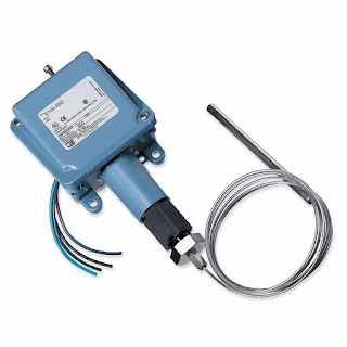 |
| UE watertight and corrosion resistant temperature switch. |
One method of changing the state of an electrical switch from open to closed in response to a process temperature change is a bulb and capillary temperature switch. The change in state occurs in the mechanical switch when the temperature of a process control operation crosses a certain threshold. Bulb and capillary switches have the advantage of operating without requiring an excitation voltage, simplifying their use in a given application.
The physical operating principle behind the capillary thermostat relies on the use of a fluid. The fluid inside the thermostat expands or contracts in response to the temperature at the sensing bulb. The change in fluid volume produces a force upon a diaphragm or other mechanical transfer device. The diaphragm is connected to, and changes the status of, an adjoining circuit using a snap action switch.
Because of their simplicity and comparatively modest cost, commercial versions of bulb and capillary switches find application throughout residential and commercial settings. Some common applications include warming ovens, deep fat fryers, and water heaters.
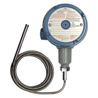 |
| UE hazardous area temperature switch. |
Industrial versions of bulb and capillary switches are fitted with appropriate housings for the installation environment. Housings designed for hazardous areas, drenching or submersion, high dust or high corrosive environments are standardly available. Many switching options exist as well, such as high current ratings, SPDT, DPDT, dual SPDT, adjustable deadbands, and internal or external adjustments.
Operation of the temperature switches is subject to a few limitations. The setpoint is most often fixed, so changing the setpoint accurately requires trial and error or a calibration procedure. The temperature range over which the switches are suitable is comparatively limited, with a matching of the bulb and capillary fluid system to the application temperature range a necessary task in product selection. Within its proper sphere of use, though, bulb and capillary temperature switches offer simple, reliable operation, with little requirement for maintenance.
Time-tested, and application proven, these simple mechanical devices are still strong candidates for applications in any temperature control process. As with any process instrument implementation, we strongly suggest you share your application requirements with a knowledgable product specialists for the best solution.
Upgrading to a United Electric (UE) Controls One Series from a Mechanical Pressure Switch
 This video below demonstrates how to replace an older on/off mechanical pressure switch and install the UE One Series.
The One Series electronic pressure and temperature transmitter-switches set the standard for smart digital process monitoring. With a fully adjustable set point and deadband and 0.1% repeatability, the One Series performs in a wide variety of applications. Available in Type 4X enclosures approved for intrinsic safety, flameproof and non-incendive area classifications, these hybrid transmitter-switches are designed to provide transmitter, switch and gauge functions all-in-one rugged enclosure that can withstand the rigors of harsh and hazardous environments.
Each One Series model incorporates intelligent self-diagnostics and can report detected faults before they become major safety issues. Plug Port Detection protects against sensor clogging. Nuisance trip filtering reduces false and spurious signals. The ability to capture pressure spikes and valleys provides process information to aid in the commissioning and debugging process.
For more information, visit http://www.ivesequipment.com or call (877) 768-1600.
When It Comes to Pressure & Temperature Switches, Understand the Difference Between Switch Normal and Process Normal
 |
| Diagram of pressure switch. Note the SPDT electrical switch on top. (Courtesy of United Electric Controls) |
 |
| Temperature switch (courtesy of United Electric Controls) |
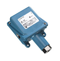 |
| Pressure switch (courtesy of United Electric Controls) |
In making the connection between the normal state of switch contacts and the normal state of a process, one should relate the switch state to the process condition which would serve as the stimulus to change the switch state. For a limit switch, which responds to physical contact by an object, normal means the target is not contacting the switch. For a proximity switch, normal means the target is far away. A normal pressure switch condition occurs when the pressure is low, or may even indicate a vacuum. Level switches are normal when the level is empty. Normal for a temperature switch means the temperature is low. Flow switches are normal when there is a low flow rate, or the fluid is stopped. Both an understanding of normal as defined by the manufacturer of the switch and normal in terms of industry specific processes is necessary to correctly interpret the status of an operation. Once the concept of normal used in everyday conversation is uncoupled from your process control thinking, things fall into place easily.
An Introduction to Industrial Pressure, Differential Pressure, and Temperature Switches
 |
| Pressure switch with large diaphragm |
This post will provide a quick introduction of industrial electromechanical pressure switches and temperature switches.
An industrial pressure and temperature switch is made up of the three main components: 1) the sensor, 2) the housing and 3) the switching element.
The correct combination of each component assures proper application of the device for its intended use.
Sensor
The sensor is located above the pressure port and process connection. For pressure and differential pressure switches, there are several varieties of pressure sensors to choose. The most common types of pressure sensors are:
Metal Bellows - an accordion-like device that provides linear expansion and contraction based upon the application of pressure or vacuum. Bellows are excellent sensors because they provide good overall pressure range and are fairly sensitive to small changes in pressure.
Piston - A rod and o-ring combination that moves linearly in direct response to applied pressure. Piston sensors are normally only applied to only very high pressure ranges. They have very small surface areas and wide deadbands (the change in pressure required to change the position of the switch output).
 |
| Pressure switch with piston sensor |
Housing
Housings are classified and selected based on the atmosphere in which they’ll be used. Housing ratings are classified by several national and international agencies such as NEMA and CENELEC. Very generally put, housings can be rated as general purpose, dust & water resistant, water tight, corrosion resistant and hazardous (explosive) environments. Proper selection of the housing is important to the operation and life expectancy of the device. In hazardous environments, proper selection is absolutely critical. If unsure about the housing classification, consultation with an applications expert is required.
Switching Element
The switching element refers to the signaling device inside the enclosure that responds to the movement of the sensor. It can be either electrical or pneumatic, and provides an on-off signal (as opposed to an analog, or proportional signal produced by transmitters).
 |
| Differential pressure switch |
For the switching element and the sensor, it is very important to know the cycling rate (number of on vs. off times over a period of time) the instrument will see. Since both of these elements are mechanical, they will eventually wear out and need to be replaced. Switches are an economical and strong performing choice for low to medium cycle rates. For extremely high cycle rates, the use of solid state transmitters are a better choice.
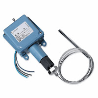 |
| Temperature switch |
An electromechanical temperature switch (sometimes called a thermostat) is, for the most part, a piston type pressure switch connected to an oil filled capillary and bulb sensing element. The thermal expansion of the oil inside the bulb and capillary creates the pressure and linear movement upon the piston sensor of the switch. The bulb and capillary elements can be supplied in copper or stainless steel, and at various lengths.
There are many more details to selecting and applying electromechanical pressure and temperature switches. This post is only intended to provide a very general introduction. It is always suggested to discuss your application with a qualified applications engineer so that you are assured to get the longest lasting, most economical and safest instrument possible.
High Performance, Low Cost, Industrial Safety Device
 |
| Safety Transmitter |
The United Electric Controls (UE) Series One is a SIL-certified (SIL stands for safety integrity level) transmitter designed solely for safety, alarm, and shutdown applications, with reliability, speed, and fewer nuisance trips. It is also designed for both greenfield and brownfield installations, and is cyber secure.
A typical safety loop consists of sensors (such as a pressure transmitter), controllers, and final control elements. Most SIL-rated pressure transmitters require 300ms to communicate with the controller and up to 500ms for the controller to send a signal to the final control element (such as a valve). This may not be fast enough for critical applications. By connecting the One Series Safety Transmitter directly connected to the final control element, the signal speed is reduced to 100ms - a huge time savings when you're in the midst of a disaster. When used with blowers, pumps and compressors, the One Series makes up a complete safety system with a self-contained sensor, controller, and final control element (the switch) capable of SIL2 without additional safety instrumented function (SIF) components.
The below document provides detailed information about the Series One.
For more information, contact:
877-768-1600
Simplifying Plant Safety instrumentation
For such point safety applications, a properly designed and implemented digital switch with self-diagnostics can be an important part of the answer. As an element of a multiple technology solution, a digital switch-based approach can help eliminate common-mode failures, significantly improve response time, achieve needed safety integrity levels (SILs), and simplify plant safety instrumentation.
To read the entire white paper, see the embedded document below:


